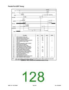
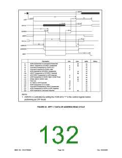
PARALLEL PORT ECP TIMING
Parallel Port FIFO (Mode 101)
The standard parallel port is run at or near the peak 500 Kbps allowed in the forward direction using DMA. The state
machine does not examine nAck and begins the next transfer based on Busy. Refer to FIGURE 23.
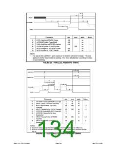
ECP Parallel Port Timing
The timing is designed to allow operation at approximately 2.0Mbytes/sec over a 15ft cable. If a shorter cable is used
then the bandwidth will increase.
Forward-Idle
When the host has no data to send it keeps HostClk (nStrobe) high and the peripheral will leave PeriphClk (Busy)
low.
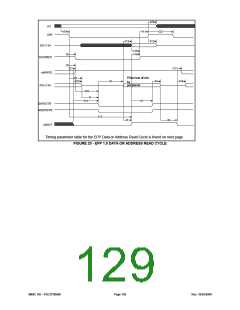
Forward Data Transfer Phase
The interface transfers data and commands from the host to the peripheral using an interlocked PeriphAck and
HostClk. The peripheral may indicate its desire to send data to the host by asserting nPeriph Request.
The Forward Data Transfer Phase may be entered from the Forward-Idle Phase. While in the Forward Phase the
peripheral may asynchronously assert the nPeriph Request (nFault) to request that the channel be reversed. When
the peripheral is not busy it sets PeriphAck (Busy) low. The host then sets HostClk (nStrobe) low when it is prepared
to send data. The data must be stable for the specified setup time prior to the falling edge of HostClk. The
peripheral then sets PeriphAck (Busy) high to acknowledge the handshake. The host then sets HostClk (nStrobe)
high. The peripheral then accepts the data and sets PeriphAck (Busy) low, completing the transfer. This sequence
is shown in FIGURE 24.
The timing is designed to provide 3 cable round-trip times for data setup if Data is driven simultaneously with HostClk
(nStrobe).
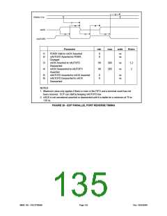
Reverse-Idle Phase
The peripheral has no data to send and keeps PeriphClk high. The host is idle and keeps HostAck low.
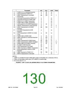
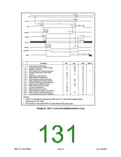
Reverse Data Transfer Phase
The interface transfers data and commands from the peripheral to the host using an interlocked HostAck and
PeriphClk.
The Reverse Data Transfer Phase may be entered from the Reverse-Idle Phase. After the previous byte has beed
accepted the host sets HostAck (nAutoFd) low. The peripheral then sets PeriphClk (nAck) low when it has data to
send. The data must be stable for the specified setup time prior to the falling edge of PeriphClk. When the host is
ready it to accept a byte it sets. HostAck (nAutoFd) high to acknowledge the handshake. The peripheral then sets
PeriphClk (nAck) high. After the host has accepted the data it sets HostAck (nAutoFd) low, completing the transfer.
This sequence is shown in FIGURE 25.
Output Drivers
To facilitate higher performance data transfer, the use of balanced CMOS active drivers for critical signals (Data,
HostAck, HostClk, PeriphAck, PeriphClk) are used ECP Mode. Because the use of active drivers can present
compatibility problems in Compatible Mode (the control signals, by tradition, are specified as open-collector), the
drivers are dynamically changed from open-collector to totem-pole. The timing for the dynamic driverchange is
specified in the IEEE 1284 Extended Capabilities Port Protocol and ISA Interface Standard, Rev. 1.14, July. 14, 1993,
available from Microsoft. The dynamic driver change must be implemented properly to prevent glitching the outputs.
SMSC DS – FDC37N3869
Page 133
Rev. 10/25/2000

 SMSC [ SMSC CORPORATION ]