CONFIGURATION
The configuration of the chip is programmable
Enter Configuration Mode
through software selectable configuration
registers.
To enter the configuration mode, two writes in
succession to port 3F0H (or 370H) with 55H
data are required. If a write to another address
or port occurs between these two writes, the
chip does not enter the configuration mode. It is
strongly recommended that interrupts be
disabled for the duration of these two writes.
CONFIGURATION REGISTER ADDRESS
The address at which the Configuration
Registers are located is controlled by the nRTS2
pin. The state of the nRTS2 pin is latched by
the trailing edge of hardware reset. If this
latched state is a 0, the Configuration Registers
are located at address 3F0H-3F1H. If the
latched state is a 1, then the Configuration
Registers are located at address 370H-371H.
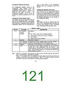
Configuration Mode
The chip contains configuration registers
CR00-CR29. These registers are accessed by
first writing the number (0-29H) of the desired
register to port 3F0H (or 370H) and then writing
or reading the configuration register through port
3F1H (or 371H).
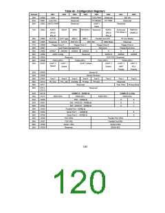
CONFIGURATION REGISTERS
The configuration registers are used to select
programmable options of the chip. After power
up, the chip is in the default mode. The default
modes are identified in the Configuration Mode
Exit Configuration Mode
The configuration mode is exited by writing an
Register
Description.
To
program
the
AAH to port 3F0H (or 370H).
configuration registers, the following sequence
must be followed:
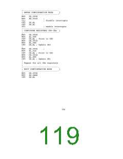
Programming Example
The following is an example of a configuration
program in Intel 8086 assembly language.
1.
2.
3.
Enter Configuration Mode.
Configure the Configuration Registers.
Exit Configuration Mode.
118

 SMSC [ SMSC CORPORATION ]