DMA Channel Select Configuration Register
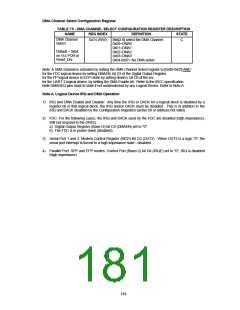
TABLE 75 - DMA CHANNEL SELECT CONFIGURATION REGISTER DESCRIPTION
NAME
REG INDEX
DEFINITION
STATE
DMA Channel
Select
0x74 (R/W)
Bits[2:0] select the DMA Channel.
0x00=DMA0
C
0x01=DMA1
0x02=DMA2
0x03=DMA3
0x04-0x07= No DMA active
Default = 0x04
on Vcc POR or
Reset_Drv
Note: A DMA channel is activated by setting the DMA Channel Select register to [0x00-0x03] AND :
for the FDC logical device by setting DMAEN, bit D3 of the Digital Output Register.
for the PP logical device in ECP mode by setting dmaEn, bit D3 of the ecr.
for the UART 2 logical device, by setting the DMA Enable bit. Refer to the IRCC specification.
Note:DMAREQ pins must tri-state if not used/selected by any Logical Device. Refer to Note A.
Note A. Logical Device IRQ and DMA Operation
1) IRQ and DMA Enable and Disable: Any time the IRQ or DACK for a logical block is disabled by a
register bit in that logical block, the IRQ and/or DACK must be disabled. This is in addition to the
IRQ and DACK disabled by the Configuration Registers (active bit or address not valid).
2) FDC: For the following cases, the IRQ and DACK used by the FDC are disabled (high impedance).
Will not respond to the DREQ.
a) Digital Output Register (Base+2) bit D3 (DMAEN) set to "0".
b) The FDC is in power down (disabled).
3) Serial Port 1 and 2: Modem Control Register (MCR) Bit D2 (OUT2) - When OUT2 is a logic "0", the
serial port interrupt is forced to a high impedance state - disabled.
4) Parallel Port: SPP and EPP modes: Control Port (Base+2) bit D4 (IRQE) set to "0", IRQ is disabled
(high impedance).
184

 SMSC [ SMSC CORPORATION ]