Configuration Registers reset to their default
values only on hard resets generated by Vcc or
VTR POR (as shown) or the RESET_DRV
signal. These registers are not affected by soft
resets.
SMSC Defined Logical Device Configuration
Registers
The
SMSC
Specific
Logical
Device
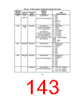
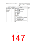
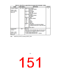
Table 59 - Floppy Disk Controller, Logical Device 0 [Logical Device Number = 0x00]
NAME
REG INDEX
DEFINITION
STATE
FDD Mode Register
0xF0 R/W Bit[0] Floppy Mode
C
= 0
= 1
Normal Floppy Mode (default)
Enhanced Floppy Mode 2 (OS2)
Default = 0x0E
Bit[1] FDC DMA Mode
on Vcc POR or
Reset_Drv
= 0
= 1
Burst Mode is enabled
Non-Burst Mode (default)
Bit[3:2] Interface Mode
= 11
= 10
= 01
= 00
AT Mode (default)
(Reserved)
PS/2
Model 30
Bit[4] Reserved
Bit[5] Reserved, set to zero
Bit[6] FDC Output Type Control
= 0
= 1
FDC outputs are OD24 open drain (default)
FDC outputs are O24 push-pull
Bit[7] FDC Output Control
= 0
= 1
FDC outputs active (default)
FDC outputs tri-stated
Note: Bits 6 & 7 do not affect the parallel port FDC
pins.
147

 SMSC [ SMSC CORPORATION ]