Fan Control Device with High Frequency PWM Support and Hardware Monitoring Features
Datasheet
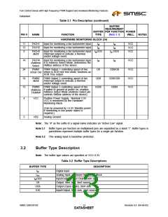
Table 3.1 Pin Description (continued)
BUFFER
REQUIREMENT
BUFFER PER FUNCTION POWER
PIN #
NAME
FUNCTION
TYPE
(Note 3.1)
WELL
NOTES
HARDWARE MONITORING BLOCK (24)
11
12
9
TACH1
TACH2
Input for monitoring a fan tachometer input.
Input for monitoring a fan tachometer input.
Input for monitoring a fan tachometer input. IMOD3
/Interrupt output to indicate a thermal
and/or voltage event.
IM
IM
IM
IM
IM /OD3
VCC
VCC
VCC
TACH3
/INT#
14
TACH4
/Address
Select
Input for monitoring a fan tachometer input.
If in Address Select Mode, determines the
SMBus address of the device.
IM
IM
VCC
24
10
13
PWM1
PWM Output 1 controlling speed of fan.
When in XOR tree test mode, functions as
XOR Tree output.
PWM Output 2 controlling speed of fan.
/Interrupt output to indicate a thermal
and/or voltage event.
PWM Output 3 controlling speed of fan.
If pulled to ground at power on, enables
Address Select Mode (Address Select pin
controls SMBus address of the device).
O8
OD8/O8
OD8/OD8
OD8/I
VCC
VCC
VCC
/xTest Out
PWM2
/INT#
OD8
IOD8
PWM3
/Address
Enable#
4
3
VCC
Positive Power Supply. Nominal 3.3V.
VCC is monitored by the Hardware
Monitoring Block.
(Can be powered by +3.3V Standby power
if monitoring in low power states is
required.)
Analog Ground.
VSS
Note: The “#” as the suffix of a signal name indicates an “Active Low” signal.
Note 3.1 Buffer types per function on multiplexed pins are separated by a slash “/”. Buffer types in
parenthesis represent multiple buffer types for a single pin function.
Note 3.2 This analog input is backdrive protected.
3.2
Buffer Type Description
Note: The buffer type values are specified at VCC=3.3V
Table 3.2 Buffer Type Descriptions
BUFFER TYPE
IM
IAN
DESCRIPTION
Digital Input
Analog Input, Hardware Monitoring Block.
Input/Output (Open Drain), 3mA sink.
Output, 8mA sink, 4mA source.
IMOD3
O8
OD8
IO8
Output (Open Drain), 8mA sink.
Input/Output, 8mA sink, 4mA source.
SMSC EMC6D103
Revision 0.4 (04-04-05)
DATA1S3HEET

 SMSC [ SMSC CORPORATION ]