Fan Control Device with High Frequency PWM Support and Hardware Monitoring Features
Datasheet
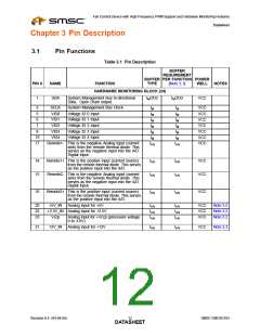
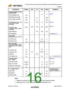
Chapter 3 Pin Description
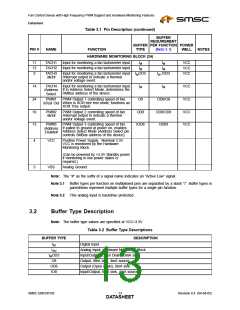
3.1
Pin Functions
Table 3.1 Pin Description
BUFFER
REQUIREMENT
BUFFER PER FUNCTION POWER
PIN #
NAME
FUNCTION
TYPE
(Note 3.1)
WELL
NOTES
HARDWARE MONITORING BLOCK (24)
1
SDA
System Management Bus bi-directional
IMOD3
IMOD3
VCC
Data. Open Drain output.
System Management Bus Clock.
Voltage ID 0 Input
2
5
6
7
8
SCLK
VID0
VID1
VID2
VID3
VID4
IM
IM
IM
IM
IM
IM
IM
IM
IM
IM
VCC
VCC
VCC
VCC
VCC
VCC
VCC
Voltage ID 1 Input
Voltage ID 2 Input
Voltage ID 3 Input
Voltage ID 4 Input
19
17
IM
IAN
IM
IAN
Remote1- This is the negative Analog input (current
sink) from the remote thermal diode. This
serves as the negative input into the A/D.
Digital Input.
18
15
Remote1+ This is the positive input (current source)
from the remote thermal diode. This serves
as the positive input into the A/D.
Remote2- This is the negative Analog input (current
sink) from the remote thermal diode. This
serves as the negative input into the A/D.
Digital Input.
IAN
IAN
VCC
VCC
IAN
IAN
16
Remote2+ This is the positive input (current source)
from the remote thermal diode. This serves
as the positive input into the A/D.
IAN
IAN
VCC
20
22
23
+5V_IN
Analog input for +5V
IAN
IAN
IAN
IAN
IAN
IAN
VCC
VCC
VCC
Note 3.2
Note 3.2
Note 3.2
+2.5V_IN Analog input for +2.5V
Vccp
Analog input for +Vccp (processor voltage:
0 to 3.0V).
21
12V_IN
Analog input for +12V
IAN
IAN
VCC
Note 3.2
Revision 0.4 (04-04-05)
SMSC EMC6D103
DATA1S2HEET

 SMSC [ SMSC CORPORATION ]