Multiple Channel 1°C Temperature Sensor with Beta Compensation
Datasheet
‘1’ - The SMBus Timeout feature is enabled. If the SMCLK line is held low for more than 30ms,
the device will reset the SMBus protocol.
Bits 6-4 - CTHRM[2:0] - Determines the number of consecutive measurements that must exceed the
corresponding Therm Limit before the THERM pin is asserted. All temperature channels use this value
to set the respective counters. The consecutive Therm counter is incremented whenever any
measurement exceed the corresponding Therm Limit.
If the temperature drops below the Therm Limit, the counter is reset. If a number of consecutive
measurements above the Therm Limit occurs, the THERM pin is asserted low.
Once the THERM pin has been asserted, the consecutive therm counter will not reset until the
corresponding temperature drops below the Therm Limit minus the Therm Hysteresis value.
The bits are decoded as shown in Table 7.13. The default setting is 4 consecutive out of limit
conversions.
Bits 3-1 - CALRT[2:0] - Determine the number of consecutive measurements that must have an out of
limit condition or diode fault before the ALERT pin is asserted. All temperature channels use this value
to set the respective counters. The bits are decoded as shown in Table 7.13. The default setting is 1
consecutive out of limit conversion.
Table 7.13 Consecutive Alert / Therm Settings
NUMBER OF CONSECUTIVE OUT OF LIMIT
2
1
0
MEASUREMENTS
1
0
0
0
(default for CALRT[2:0])
0
0
0
1
1
1
2
3
4
1
1
1
(default for CTHRM[2:0])
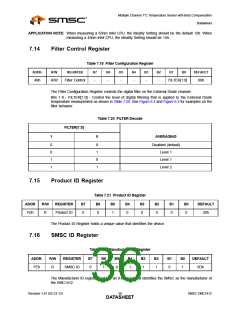
7.12
Beta Configuration Register
Table 7.14 Beta Configuration Register
ADDR.
R/W
REGISTER
B7
B6
B5
B4
B3
B2
B1
B0
DEFAULT
External
Diode Beta
Configuration
25h
R/W
-
-
-
-
ENABLE
BETA[2:0]
08h
This register is used to set the Beta Compensation factor that is used for the external diode channel.
Bit 3 - ENABLE - Enables the Beta Compensation factor auto-detection function.
‘0’ - The Beta Compensation Factor auto-detection circuitry is disabled.
‘1’ (default) - The Beta Compensation factor auto-detection circuitry is enabled. At the beginning of
every conversion, the optimal Beta Compensation factor setting will be determined and applied.
The BETA[2:0] bits will be automatically updated to indicate the current setting.
Bit 2-0 - BETA[2:0] - These bits always reflect the current beta configuration settings. If auto-detection
circuitry is enabled, these bits will be updated automatically and writing to these bits will have no effect.
If the auto-detection circuitry is disabled, these bits will determine the beta configuration setting.
Care should be taken when setting the BETA[2:0] bits when the auto-detection circuitry is disabled. If
the Beta Compensation factor is set at a beta value that is higher than the transistor beta, the circuit
SMSC EMC1412
Revision 1.41 (02-23-12)
DATA3S3HEET

 SMSC [ SMSC CORPORATION ]