1°C Triple SMBus Sensor with Resistance Error Correction
Datasheet
The EMC1033 uses an interlock mechanism that locks the low byte value when the high byte register
is read. This prevents updates to the low byte register between high byte and low byte reads. This
interlock mechanism requires that the high byte register always be read prior to reading the low byte
register.
4.9
Status Register
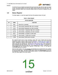
The status register is a read only register that stores the operational status of the part.
Table 4.4 Status Register
STATUS REGISTER
BIT
NAME
FUNCTION
7
6
5
4
3
2
1
0
Busy
LHIGH
LLOW
1 when ADC is converting
1 when Internal Temperature High Limit is exceeded
1 when Internal Temperature Low Limit is exceeded
1 when Remote 1 Temperature High Limit is exceeded
1 when Remote 1 Temperature Low Limit is exceeded
1 when Remote 1 or Remote 2 is open circuit
1 when Remote 1 THERM Limit is exceeded
R1HIGH
R1LOW
FAULT
R1THRM
LTHRM
1 when Internal THERM Limit is exceeded
Bit 7 indicates that the ADC is busy converting a value. Bits 6 and 5 indicate that the internal
temperature is above or below its high or low limits respectively. Likewise, bits 4 and 3 indicate that
remote 1 temperature is above or below its limits. See Section 4.13, "Limit Registers," on page 17 for
detail on the limits are compared. Bit 2 indicates that an open circuit on one, or both, remote diode
anode connections has been detected. See Section 4.15, "Diode Fault Register" for information on
how to determine which diode has a fault. Bits 1 and 0 indicate that the remote 1 temperature or the
internal temperature has exceeded their respective THERM limits. If bits 1 or 0 go high the
ADDR/THERM signal will be asserted.
When the status register is read, bits 2 through 6 will individually clear provided that the error condition
for that bit no longer exists. The ALERT/THERM2 output is latched and will not be reset until the host
has responded to the SMBALERT# with an alert response address. The ALERT/THERM2 signal will not
reset if the status register has not been cleared.
SMSC EMC1033
Revision 1.1 (01-19-07)
DATA1S5HEET

 SMSC [ SMSC CORPORATION ]