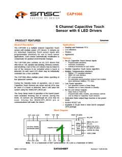
6 Channel Capacitive Touch Sensor with 6 LED Drivers
Datasheet
List of Figures
Figure 1.1 CAP1066 Pin Diagram (20-Pin QFN) . . . . . . . . . . . . . . . . . . . . . . . . . . . . . . . . . . . . . . . . . . . 8
Figure 3.1 SMBus Timing Diagram . . . . . . . . . . . . . . . . . . . . . . . . . . . . . . . . . . . . . . . . . . . . . . . . . . . . . 16
Figure 3.1 SPI Timing . . . . . . . . . . . . . . . . . . . . . . . . . . . . . . . . . . . . . . . . . . . . . . . . . . . . . . . . . . . . . . . 19
Figure 3.1 Example SPI Bus Communication - Normal Mode . . . . . . . . . . . . . . . . . . . . . . . . . . . . . . . . 21
Figure 3.2 SPI Reset Interface Command - Normal Mode . . . . . . . . . . . . . . . . . . . . . . . . . . . . . . . . . . . 22
Figure 3.3 SPI Set Address Pointer Command - Normal Mode . . . . . . . . . . . . . . . . . . . . . . . . . . . . . . . 22
Figure 3.4 SPI Write Command - Normal Mode . . . . . . . . . . . . . . . . . . . . . . . . . . . . . . . . . . . . . . . . . . . 23
Figure 3.5 SPI Read Command - Normal Mode . . . . . . . . . . . . . . . . . . . . . . . . . . . . . . . . . . . . . . . . . . . 23
Figure 3.6 SPI Read Command - Normal Mode - Full . . . . . . . . . . . . . . . . . . . . . . . . . . . . . . . . . . . . . . 24
Figure 3.7 SPI Reset Interface Command - Bi-directional Mode . . . . . . . . . . . . . . . . . . . . . . . . . . . . . . 24
Figure 3.8 SPI Set Address Pointer Command - Bi-directional Mode. . . . . . . . . . . . . . . . . . . . . . . . . . . 25
Figure 3.9 SPI Write Data Command - Bi-directional Mode . . . . . . . . . . . . . . . . . . . . . . . . . . . . . . . . . . 25
Figure 3.10 SPI Read Data Command - Bi-directional Mode . . . . . . . . . . . . . . . . . . . . . . . . . . . . . . . . . . 25
Figure 4.1 System Diagram for CAP1066. . . . . . . . . . . . . . . . . . . . . . . . . . . . . . . . . . . . . . . . . . . . . . . . 28
Figure 4.2 Sensor Interrupt Behavior - Repeat Rate Enabled. . . . . . . . . . . . . . . . . . . . . . . . . . . . . . . . . 31
Figure 4.3 Sensor Interrupt Behavior - No Repeat Rate Enabled. . . . . . . . . . . . . . . . . . . . . . . . . . . . . . 31
Figure 5.1 Pulse Behavior with Non-Inverted Polarity. . . . . . . . . . . . . . . . . . . . . . . . . . . . . . . . . . . . . . . 58
Figure 5.2 Pulse Behavior with Inverted Polarity. . . . . . . . . . . . . . . . . . . . . . . . . . . . . . . . . . . . . . . . . . . 58
Figure 5.3 Pulse 2 Behavior with Non-Inverted Polarity . . . . . . . . . . . . . . . . . . . . . . . . . . . . . . . . . . . . . 60
Figure 5.4 Pulse 2 Behavior with Inverted Polarity . . . . . . . . . . . . . . . . . . . . . . . . . . . . . . . . . . . . . . . . . 60
Figure 5.5 Direct Mode Behavior for Non-Inverted Polarity. . . . . . . . . . . . . . . . . . . . . . . . . . . . . . . . . . . 64
Figure 5.6 Direct Mode Behavior for Inverted Polarity . . . . . . . . . . . . . . . . . . . . . . . . . . . . . . . . . . . . . . 65
Figure 6.1 20-Pin QFN 4mm x 4mm Package Drawing . . . . . . . . . . . . . . . . . . . . . . . . . . . . . . . . . . . . . 66
Figure 6.2 20-Pin QFN 4mm x 4mm Package Dimensions. . . . . . . . . . . . . . . . . . . . . . . . . . . . . . . . . . . 67
Figure 6.3 20-Pin QFN 4mm x 4mm PCB Drawing. . . . . . . . . . . . . . . . . . . . . . . . . . . . . . . . . . . . . . . . . 67
Figure 6.4 CAP1066 Package Markings . . . . . . . . . . . . . . . . . . . . . . . . . . . . . . . . . . . . . . . . . . . . . . . . . 68
SMSC CAP1066
5
Revision 1.1 (08-05-09)
DATASHEET

 SMSC [ SMSC CORPORATION ]