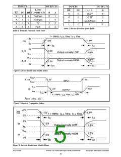
INPUTS
OUTPUTS
INPUTS
OUTPUTS
LINE
RE DE DI CONDITION
RE
DE
0
A - B
+0.2V
R
1
B
0
A
1
0
0
0
1
X
X
X
X
1
1
0
1
1
0
No Fault
No Fault
X
0
-0.2V
0
1
0
0
Inputs Open
X
1
X
X
Z
Z
Z
Z
0
Z
Fault
Table 2. Receive Function Truth Table
Table 1. Transmit Function Truth Table
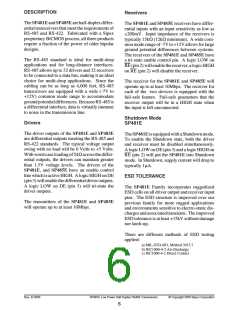
f = 1MHz; tR < 10ns; tF < 10ns
1.5V
+3V
1.5V
DE
0V
tZL
2.3V
tLZ
5V
A, B
Output normally LOW
Output normally HIGH
0.5V
0.5V
VOL
VOH
A, B
2.3V
tZH
0V
tHZ
Figure 6. Driver Enable and Disable Times
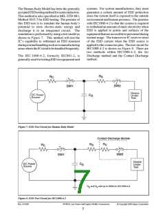
+
–
V0D2
0V
0V
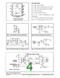
A – B
R
INPUT
V0D2
VOH
VOL
1.5V
1.5V
OUTPUT
tPLH
tPHL
f = 1MHz; tR < 10ns; tF < 10ns
tSKEW = tPHL - tPLH
|
|
Figure 7. Receiver Propagation Delays
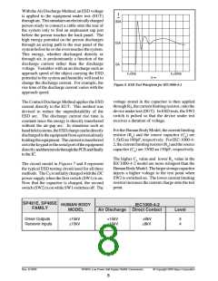
+3V
1.5V
1.5V
RE
R
f = 1MHz; t < 10ns; t < 10ns
R
F
0V
5V
t
t
LZ
ZL
1.5V
Output normally LOW
Output normally HIGH
0.5V
0.5V
V
IL
V
IH
R
1.5V
0V
t
t
HZ
ZH
Figure 8. Receiver Enable and Disable Times
Rev. 5/16/03
SP481E Low Power Half-Duplex RS485 Transceivers
© Copyright 2003 Sipex Corporation
5

 SIPEX [ SIPEX CORPORATION ]