EFR32MG13 Mighty Gecko Multi-Protocol Wireless SoC Family Data Sheet
Pin Definitions
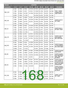
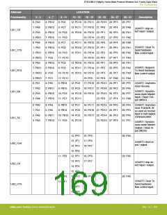
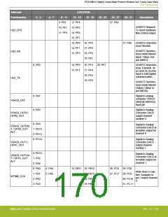
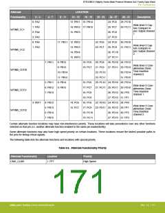
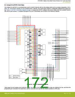
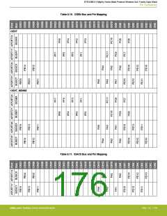
6.6 Analog Port (APORT) Client Maps
The Analog Port (APORT) is an infrastructure used to connect chip pins with on-chip analog clients such as analog comparators, ADCs,
DACs, etc. The APORT consists of a set of shared buses, switches, and control logic needed to configurably implement the signal rout-
ing. Figure 6.4 APORT Connection Diagram on page 172 shows the APORT routing for this device family (note that available features
may vary by part number). A complete description of APORT functionality can be found in the Reference Manual.
1X
2X
3X
4X
NEXT1
NEXT0
1X
2X
3X
4X
NEXT1
NEXT0
POS
NEG
POS
NEG
PB15
PF0
ACMP1
PB14
PB13
PF1
PF2
1Y
2Y
3Y
4Y
NEXT1
NEXT0
ACMP0
1Y
2Y
3Y
4Y
OPA2_N
OUT2
PF3
PF4
NEXT1
NEXT0
1X
2X
3X
4X
NEXT0
NEXT2
PB12
PB11
PF5
PF6
PF7
POS
NEG
OPA2_P
1Y
2Y
3Y
4Y
ADC0
1X
1Y
IDAC0
NEXT1
EXTP
EXTN
OPA1_P
1X
PA5
PA4
VDAC0_OUT0ALT
VDAC0_OUT1ALT
POS
NEG
OPA0_P
1X
2X
3X
4X
2X
3X
4X
OUT0ALT
OPA0_N
POS
NEG
OPA1_N
1Y
OUT1ALT
OUT0
OPA0_N
1Y
2Y
3Y
4Y
2Y
3Y
4Y
OPA1
PA3
PA2
OPA0
OPA0_P
OUT1
OUT1ALT
OUT1
VDAC0_OUT1ALT
OUT0
OUT0ALT
OUT1
OUT2
OUT3
OUT1ALT
ADC_EXTP
OUT
OUT2
OUT3
OUT4
OUT
PA1
PA0
NEXT1
ADC_EXTN
OUT4
NEXT0
OPA2_P
1X
2X
3X
4X
OPA1_N
PD15
POS
NEG
VDAC0_OUT0ALT
OUT0ALT
OPA2_N
1Y
2Y
OPA2
3Y
4Y
OUT2
OUT2ALT
OUT1
OUT2
OUT
OUT3
OUT4
NEXT2
1X
1Y
3X
3Y
CEXT
CSEN
2X
2Y
CEXT_SENSE
4X
4Y
nX, nY
APORTnX, APORTnY
AX, BY, …
BUSAX, BUSBY, ...
Figure 6.4. APORT Connection Diagram
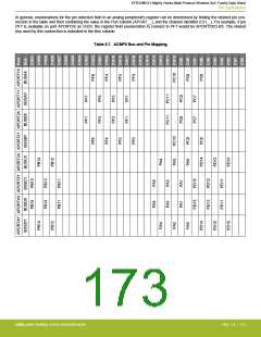
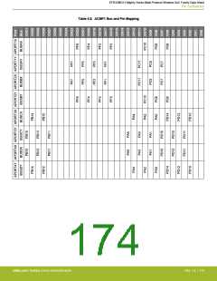
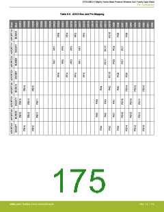
Client maps for each analog circuit using the APORT are shown in the following tables. The maps are organized by bus, and show the
peripheral's port connection, the shared bus, and the connection from specific bus channel numbers to GPIO pins.
silabs.com | Building a more connected world.
Rev. 1.4 | 172

 SILICON [ SILICON ]