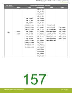
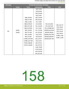
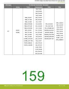
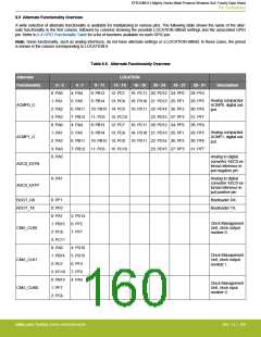
EFR32MG13 Mighty Gecko Multi-Protocol Wireless SoC Family Data Sheet
Pin Definitions
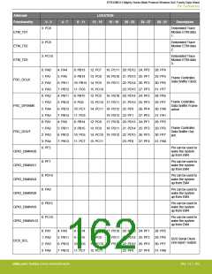
Alternate
LOCATION
12 - 15 16 - 19
Functionality
0 - 3
4 - 7
8 - 11
20 - 23
24 - 27
28 - 31
Description
0: PF0
Debug-interface
Serial Wire clock
input and JTAG
Test Clock.
DBG_SWCLKTCK
DBG_SWDIOTMS
DBG_SWO
Note that this func-
tion is enabled to
the pin out of reset,
and has a built-in
pull down.
0: PF1
Debug-interface
Serial Wire data in-
put / output and
JTAG Test Mode
Select.
Note that this func-
tion is enabled to
the pin out of reset,
and has a built-in
pull up.
0: PF2
Debug-interface
Serial Wire viewer
Output.
1: PB13
2: PD15
3: PC11
Note that this func-
tion is not enabled
after reset, and
must be enabled by
software to be
used.
0: PF3
Debug-interface
JTAG Test Data In.
Note that this func-
tion becomes avail-
able after the first
valid JTAG com-
mand is received,
and has a built-in
pull up when JTAG
is active.
DBG_TDI
0: PF2
Debug-interface
JTAG Test Data
Out.
Note that this func-
tion becomes avail-
able after the first
valid JTAG com-
mand is received.
DBG_TDO
1: PA5
3: PC6
3: PC7
Embedded Trace
Module ETM clock .
ETM_TCLK
ETM_TD0
Embedded Trace
Module ETM data
0.
silabs.com | Building a more connected world.
Rev. 1.4 | 161

 SILICON [ SILICON ]