EFM32G Data Sheet
System Overview
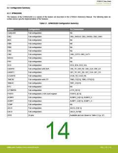
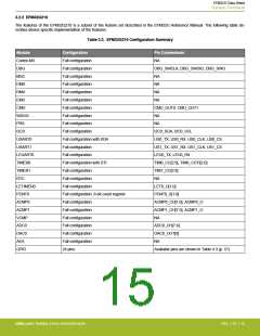
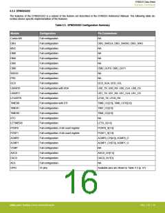
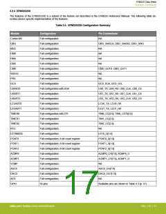
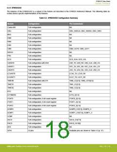
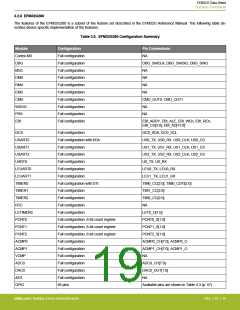
3.2.2 EFM32G210
The features of the EFM32G210 is a subset of the feature set described in the EFM32G Reference Manual. The following table de-
scribes device specific implementation of the features.
Table 3.2. EFM32G210 Configuration Summary
Module
Cortex-M3
DBG
Configuration
Pin Connections
Full configuration
Full configuration
Full configuration
Full configuration
Full configuration
Full configuration
Full configuration
Full configuration
Full configuration
Full configuration
Full configuration with IrDA
Full configuration
Full configuration
Full configuration with DTI
Full configuration
Full configuration
Full configuration
Full configuration, 8-bit count register
Full configuration
Full configuration
Full configuration
Full configuration
Full configuration
Full configuration
24 pins
NA
DBG_SWCLK, DBG_SWDIO, DBG_SWO
MSC
NA
DMA
NA
RMU
NA
EMU
NA
CMU
CMU_OUT0, CMU_OUT1
WDOG
PRS
NA
NA
I2C0
I2C0_SDA, I2C0_SCL
US0_TX, US0_RX. US0_CLK, US0_CS
US1_TX, US1_RX, US1_CLK, US1_CS
LEU0_TX, LEU0_RX
TIM0_CC[2:0], TIM0_CDTI[2:0]
TIM1_CC[2:0]
USART0
USART1
LEUART0
TIMER0
TIMER1
RTC
NA
LETIMER0
PCNT0
ACMP0
ACMP1
VCMP
ADC0
LET0_O[1:0]
PCNT0_S[1:0]
ACMP0_CH[1:0], ACMP0_O
ACMP1_CH[7:5], ACMP1_O
NA
ADC0_CH[7:4]
DAC0
DAC0_OUT[0]
AES
NA
GPIO
Available pins are shown in Table 4.3 (p. 57)
silabs.com | Building a more connected world.
Rev. 2.10 | 15

 SILICON [ SILICON ]