BATTERY PROTECTION IC FOR 1-CELL PACK
S-8211C Series
Rev.5.0_00
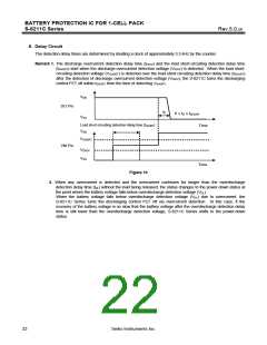
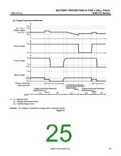
5. Charge Overcurrent Status
When a battery in the normal status is in the status where the voltage of the VM pin is lower than the charge
overcurrent detection voltage because the charge current is higher than the specified value and the status lasts for
the charge overcurrent detection delay time, the charge control FET is turned off and charging is stopped. This
status is called the charge overcurrent status.
This IC will be restored to the normal status from the charge overcurrent status when, the voltage at the VM pin
returns to charge overcurrent detection voltage (VCIOV) or higher by removing the charger.
The charge overcurrent detection function does not work in the overdischarge status.
The resistance (RVMD) between the VM pin and VDD pin, and the resistance (RVMS) between the VM pin and VSS pin
are not connected in the charge overcurrent status.
6. 0 V Battery Charging Function “Available”
This function is used to recharge a connected battery whose voltage is 0 V due to self-discharge. When the 0 V
battery charge starting charger voltage (V0CHA) or a higher voltage is applied between the EB+ and EB− pins by
connecting a charger, the charging control FET gate is fixed to the VDD pin voltage.
When the voltage between the gate and source of the charging control FET becomes equal to or higher than the turn-
on voltage due to the charger voltage, the charging control FET is turned on to start charging. At this time, the
discharging control FET is off and the charging current flows through the internal parasitic diode in the discharging
control FET. When the battery voltage becomes equal to or higher than overdischarge release voltage (VDU), the S-
8211C Series enters the normal status.
Caution 1. Some battery providers do not recommend charging for a completely self-discharged battery.
Please ask the battery provider to determine whether to enable or inhibit the 0 V battery
charging function.
2. The 0 V battery charge function has higher priority than the charge overcurrent detection
function. Consequently, a product in which use of the 0 V battery charging function is enabled
charges a battery forcibly and the charge overcurrent cannot be detected when the battery
voltage is lower than overdischarge detection voltage (VDL).
7. 0 V Battery Charging Function “Unavailable”
This function inhibits recharging when a battery that is internally short-circuited (0 V battery) is connected. When the
battery voltage is the 0 V battery charge inhibition battery voltage (V0INH) or lower, the charging control FET gate is
fixed to the EB− pin voltage to inhibit charging. When the battery voltage is the 0 V battery charge inhibition battery
voltage (V0INH) or higher, charging can be performed.
Caution Some battery providers do not recommend charging for a completely self-discharged battery.
Please ask the battery provider to determine whether to enable or inhibit the 0 V battery charging
function.
Seiko Instruments Inc.
21

 SII [ SEIKO INSTRUMENTS INC ]