PC123/PC123F
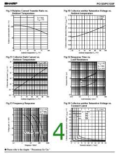
Fig. 9 Relative Current Transfer Ratio vs.
Fig.10 Collector-emitter Saturation Voltage vs.
Ambient temperature
Ambient Temperature
150
0.16
IF = 20mA
IF = 5mA
VCE = 5V
I
c = 1mA
0.14
0.12
0.10
0.08
0.06
0.04
0.02
0.00
100
50
0
- 30
0
25
50
75
100
- 30
0
20
40
60
(
80
)
100
(
)
Ambient temperature T a ˚C
Ambient temperature T a ˚C
Fig.11 Collector Dark Current vs.
Ambient Temperature
Fig.12 Response Time vs.
Load Resistance
1000
- 5
10
VCE= 50V
5
V
CE = 2V
IC = 2mA
T a= 25˚C
- 6
5
10
10
10
10
100
- 7
5
tr
tf
- 8
5
10
td
- 9
5
ts
1
- 10
5
10
- 11
0.1
0.01
10
- 30
0
20
40
60
80
100
0.1
1
10
100
(
)
(
)
Ambient temperature T a ˚C
Load resistance k Ω
Fig.13 Frequency Response
Fig.14 Collector-emitter Saturation Voltage vs.
Forward Currnt
5
V
CE = 5V
T
a= 25˚C
5.0
4.5
4.0
3.5
3.0
2.5
2.0
1.5
1.0
0.5
0
I
C = 2mA
I
C = 0.5mA
1mA
3mA
5mA
7mA
T
a= 25˚C
0
- 5
- 10
RL = 10k Ω
100 Ω
1k Ω
- 15
- 20
0.1
1
10
100
1000
0
2
4
6
8
10 12 14 16 18 20
(
)
(
)
mA
Frequency kHz
Forward current I
F
Please refer to the chapter “Precautions for Use ”
●

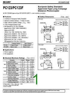
 SHARP [ SHARP ELECTRIONIC COMPONENTS ]