PC123/PC123F
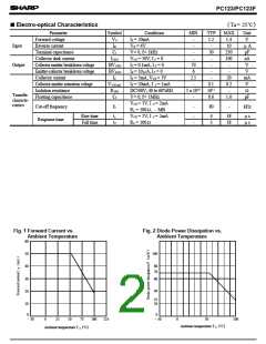
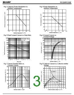
Fig. 3 Collector Power Dissipation vs.
Fig. 4 Power Dissipation vs.
Ambient Temperature
Ambient Temperature
200
250
200
150
100
150
100
50
50
0
0
- 30
- 30
0
25
50
75
100
125
0
25
50
75
100
125
(
)
Ambient temperature T a ˚C
(
)
Ambient temperature T a ˚C
Fig. 5 Peak Forward Current vs. Duty Ratio
Fig. 6 Forward Current vs.
Forward Voltage
1000
10000
Pulse width <=100µs
500
5000
Ta = 25˚C
+ 25˚C
2000
1000
200
T a = 75˚C
100
- 25˚C
500
200
100
50
50˚C
0˚C
20
10
5
50
20
2
1
10
5
- 3
- 2
- 1
2
2
2
5
5
5
5
10
10
10
1
0
0.5
1.0
1.5
2.0
2.5
3.0
(
)
Forward voltage V F
V
Duty ratio
Fig. 7 Current Transfer Ratio vs.
Fig. 8 Collector Current vs. Collector-emitter
Voltage
Forward Current
300
VCE = 5V
T a= 25˚C
T a = 25˚C
60
250
200
150
100
54
(
)
PC MAX.
48
42
36
30
24
18
12
6
50
0
0
0
0.1
1
10
100
1
2
3
4
5
6
7
8
9
10
(
)
(
)
Forward current I
mA
Collector-emitter voltage VCE
V
F

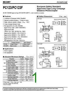
 SHARP [ SHARP ELECTRIONIC COMPONENTS ]