SX1232
WIRELESS & SENSING
4.5. Top Level Sequencer
DATASHEET
Depending on the application, it is desirable to be able to change the mode of the circuit according to a predefined
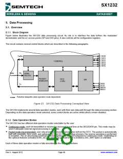
sequence without access to the serial interface. In order to define different sequences or scenarios, a user-programmable
state machine, called Top Level Sequencer (Sequencer in short), can automatically control the chip modes.
The Sequencer is activated by setting the SequencerStart bit in RegSeqConfig1 to 1 in Sleep or Standby mode (called
initial mode).
It is also possible to force the Sequencer off by setting the Stop bit in RegSeqConfig1 to 1 at any time.
Note SequencerStart and Stop bit must never be set at the same time.
4.5.1. Sequencer States
The Sequencer takes control of the chip operation over 4 possible states and 3 transitory states:
Table 23 Sequencer States
Sequencer
Description
State
The Sequencer is not activated. Sending a SequencerStart command will launch it.
SequencerOff State
Idle State
When coming from LowPowerSelection state, the Sequencer will be Off, whilst the chip will
return to its initial mode (either Sleep or Standby mode).
The chip is in low-power mode, either Standby or Sleep, as defined by IdleMode in
RegSeqConfig1. The Sequencer waits only for the T1 interrupt.
Transmit State
Receive State
PacketReceived
The transmitter in on.
The receiver in on.
The receiver is on and a packet has been received. It is stored in the FIFO.
LowPowerSelection Selects low power state (SequencerOff or Idle State)
RxTimeout
Defines the action to be taken on a RxTimeout interrupt.
RxTimeout interrupt can be a TimeoutRxRssi, TimeoutRxPreamble or TimeoutSignalSync
interrupt.
Rev 3 - August 2012
Page 44
www.semtech.com

 SEMTECH [ SEMTECH CORPORATION ]