SK44XX Family
Quad Buffer/Receiver
HIGH-PERFORMANCE PRODUCTS
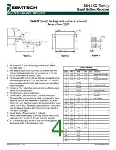
SK44XX ꢀamily Package Information (continued)
5mm x 5mm TQꢀP
02
WITH
PLATING
2
9
7
b
R1
01
e / 2
ꢁ
ꢀ
R2
S
GAGE PLANE
03
ꢁ
11
00
L
ꢀ
b
See Detail in
Figure 2
9
b1
(L1)
Figure 3.
Figure 1.
Figure 2.
1. All dimensions and tolerancing conforms to ANSI
Y14.5M-1982.
2. The top package body size may be smaller than the
bottom package body size by as much as 0.15 mm.
3. To be determined at seating plane.
4. Dimensions D1 and E1 do not include mold protrusion.
Allowable protrusion is 0.25 mm per side. D1 and E1
are maximum plastic body size dimensions including
mold mismatch.
5. Details of Pin 1 identifier optional, but must be located
within the zone indicated.
JEDEC Variation
All Dimensions in Millimeters
Symbol
A
MIN
1.00
0.05
0.95
NOM
1.10
0.10
1.00
7.00 BSC
5.00 BSC
7.00 BSC
5.00 BSC
32
MAX
1.20
0.15
1.05
Note Comments
Package Stand Off Height
Air Gap
A1
A2
D
Package Body Thickness
3
D1
E
4, 2 Package Body Length
3
E1
N
4, 2 Package Body Width
Lead Count
6. All dimensions are in millimeters.
e
0.50 BSC
0.22
0.20
–
Lead Pitch
7. Dimension b does not include Dambar protrusion.
Allowable Dambar protrusion shall not cause the lead
width to exceed the maximum b dimension by more
b
0.17
0.17
0.08
0.08
0o
0.27
0.23
–
7
Lead Thickness
b1
R1
R2
00
01
02
03
S
than 0.08 mm. Dambar cannot be located on the lower
radius or the foot. Minimum space between protrusion
and an adjacent lead is 0.07 mm for 0.4 mm and 0.5
mm pitch packages.
–
0.20
7o
3.5o
0o
–
–
8. Exact shape of each corner is optional.
11o
12o
13o
13o
–
9. These dimensions apply to the flat section of the lead
between 0.10 mm and 0.25 mm from the lead tip.
10.A1 is defined as the distance from the seating plane to
the lowest point of the package body.
11o
12o
0.20
0.09
0.09
0.45
–
c
–
0.20
0.16
0.75
c1
L
–
0.60
1.00 REF
0.20
0.20
0.08
0.08
L1
aaa
bbb
ccc
ddd
Revision 1/July 10, 2002
www.semtech.com
4

 SEMTECH [ SEMTECH CORPORATION ]