STK672-080
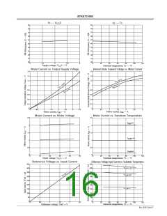
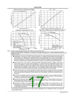
Motor Current vs. Reference Voltage
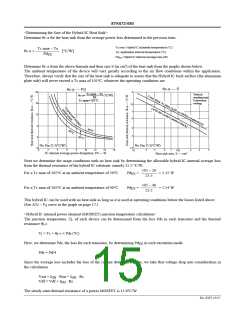
∆Tc — Pd
2
1.8
1.6
1.4
1.2
1
80
70
60
VCC1: 24 V motor: PK264-02B
50
40
0.8
0.6
0.4
30
20
10
0
0.2
0
0
0.5
1
1.5
2
2.5
0
0.5
1
1.5
2
2.5
3
3.5
Motor current, I — A
Hybrid IC internal average power dissipation, Pd — W
OH
Motor Current (IOH) Derating Curves for the Operating Substrate Temperature Tc
Substrate Temperature Rise Test
60
50
40
30
3.5
2W1-2ex
3
2.5
2
2ex
1.5
1
V
1 : 24V
CC
Test motor : PK264-02B
Motor current :
20
10
0
I
:
OH
Motor voltage: 24 V
Motor resistance (R): 0.4 Ω
Inductance (L): 1.2 mH
2-phase excitation: 1.5 A
2W1-2 phase excitation: 2 A
With no heat sink
0.5
0
0
2
3
5
7
2
3
5
7
2
3
5
7
0
20
40
60
80
100
120
1000
10000
100000
Operating substrate temperature, Tc — °C
CLK frequency, PPS - Hz
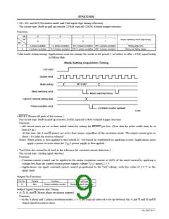
Notes • The above current ranges apply when the output voltage is not in the avalanche state.
•
The above operating substrate temperatures (Tc) are measured when the motor is operating. Since Tc will vary depending on the ambient
temperature (Ta), the value of IOH, and whether IOH is continuous or intermittent, the actual values of Tc must be verified (measured) in an actual
operating end product.
Specifications of any and all SANYO products described or contained herein stipulate the performance,
characteristics, and functions of the described products in the independent state, and are not guarantees
of the performance, characteristics, and functions of the described products as mounted in the customer’s
products or equipment. To verify symptoms and states that cannot be evaluated in an independent device,
the customer should always evaluate and test devices mounted in the customer’s products or equipment.
SANYO Electric Co., Ltd. strives to supply high-quality high-reliability products. However, any and all
semiconductor products fail with some probability. It is possible that these probabilistic failures could
give rise to accidents or events that could endanger human lives, that could give rise to smoke or fire,
or that could cause damage to other property. When designing equipment, adopt safety measures so
that these kinds of accidents or events cannot occur. Such measures include but are not limited to protective
circuits and error prevention circuits for safe design, redundant design, and structural design.
In the event that any or all SANYO products (including technical data, services) described or contained
herein are controlled under any of applicable local export control laws and regulations, such products must
not be exported without obtaining the export license from the authorities concerned in accordance with the
above law.
No part of this publication may be reproduced or transmitted in any form or by any means, electronic or
mechanical, including photocopying and recording, or any information storage or retrieval system,
or otherwise, without the prior written permission of SANYO Electric Co., Ltd.
Any and all information described or contained herein are subject to change without notice due to
product/technology improvement, etc. When designing equipment, refer to the “Delivery Specification”
for the SANYO product that you intend to use.
Information (including circuit diagrams and circuit parameters) herein is for example only; it is not
guaranteed for volume production. SANYO believes information herein is accurate and reliable, but
no guarantees are made or implied regarding its use or any infringements of intellectual property rights
or other rights of third parties.
This catalog provides information as of May, 2004. Specifications and information herein are subject to
change without notice.
PS No. 6507-17/17

 SANYO [ SANYO SEMICON DEVICE ]