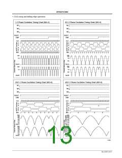
STK672-080
Thermal Design
<Hybrid IC Average Internal Power Loss Pd>
The main elements internal to this hybrid IC with large average power losses are the current control devices, the
regenerative current diodes, and the current detection resistor. Since sine wave drive is used, the average power loss
during microstepping drive can be approximated by applying a waveform factor of 0.64 to the square wave loss during 2
phase excitation.
The losses in the various excitation modes are as follows.
fclock
I
· fclock
OH
2 phase excitation
Pd
Pd
Pd
Pd
Pd
= (Vsat + Vdf) · ——— · I · t2 + ————— · (Vsat · t1 + Vdf · t3)
2EX
OH
2
2
fclock
I
OH
· fclock
1-2 phase excitation
W1-2 phase excitation
2W1-2 phase excitation
4W1-2 phase excitation
= 0.64 · {(Vsat + Vdf) · ——— · I · t2 + ————— · (Vsat · t1 + Vdf · t3)}
1-2EX
OH
4
4
fclock
I
OH
· fclock
= 0.64 · {(Vsat + Vdf) · ——— · I · t2 + ————— · (Vsat · t1 + Vdf · t3)}
W1-2EX
2W1-2EX
4W1-2EX
OH
8
8
fclock
I
· fclock
OH
= 0.64 · {(Vsat + Vdf) · ——— · I · t2 + ————— · (Vsat · t1 + Vdf · t3)}
OH
16
16
fclock
I
· fclock
OH
= 0.64 · {(Vsat + Vdf) · ——— · I · t2 + ————— · (Vsat · t1 + Vdf · t3)}
OH
16
16
Here, t1 and t3 can be determined from the same formulas for all excitation methods.
–L
R + 0.35
–L
V
1 + 0.35
CC
t1 = ———— · n (1 – ————— · I
)
OH
t3 = —— · n (——————————)
R + 0.35
V 1
CC
R
I
· R + V 1 + 0.35
OH
CC
However, the formula for t2 differs with the excitation method.
2
2 phase excitation t2 = ——— – (t1 +t3)
fclock
3
1-2 phase excitation t2 = ——— – t1
fclock
7
W1-2 phase excitation t2 = ——— – t1
fclock
15
2W1-2 phase excitation
4W1-2 phase excitation
t2 = ——— – t1
fclock
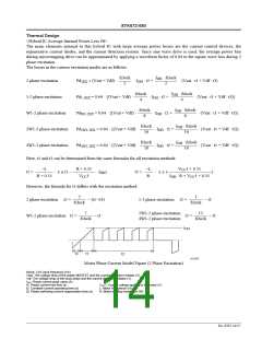
I
OH
t3
t1
t2
A13270
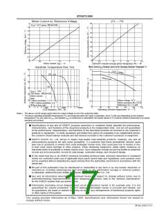
Motor Phase Current Model Figure (2 Phase Excitation)
fclock: CLK input frequency (Hz)
Vsat: The voltage drop of the power MOSFET and the current detection resistor (V)
Vdf: The voltage drop of the body diode and the current detection resistor (V)
IOH: Phase current peak value (A)
t1: Phase current rise time (s)
VCC1: Supply voltage applied to the motor (V)
t2: Constant-current operating time (s)
t3: Phase switching current regeneration time (s)
L: Motor inductance (H)
R: Motor winding resistance (W)
No. 6507-14/17

 SANYO [ SANYO SEMICON DEVICE ]