LC866548/40/32/28/24A
(8) Timers
- Timer 0 : 16-bit timer/counter with 2-bit prescaler + 8-bit programmable prescaler
Mode 0 : Two 8-bit timers with programmable prescaler
Mode 1 : 8-bit timer with a programmable prescaler + 8-bit counter
Mode 2 : 16-bit timer with a programmable prescaler
Mode 3 : 16-bit counter
The resolution of Timer is tCYC. (tCYC : cycle time)
- Timer 1 : 16-bit timer/PWM with
Mode 0 : Two 8-bit timers
Mode 1 : 8-bit timer + 8-bit PWM
Mode 2 : 16-bit timer
Mode 3 : Variable-bit PWM (9-16 bits)
In Mode 0 and Mode 1, the resolution of Timer and PWM is tCYC.
In Mode 2 and Mode 3, the resolution of Timer and PWM selectable : tCYC or 1/2tCYC by program
- Base timer
Every 500ms overflow system for a clock application (using 32.768kHz crystal oscillation for Base timer
clock)
Every 976 s, 3.9ms, 15.6ms, 62.5ms overflow system (using 32.768kHz crystal oscillation for Base timer
µ
clock)
The Base timer clock selectable ; 32.768kHz crystal oscillation, System clock, and programmable prescaler
output of Timer 0
(9) Buzzer output
- The Buzzer sound frequency selectable ; 4kHz, 2kHz (using 32.768kHz crystal oscillation for Base timer clock)
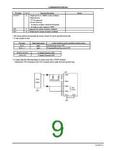
(10) Remote control receiver circuit (connected to the P73/INT3/T0IN terminal)
- Noise rejection function (the time constant of noise rejection filter : 1tCYC/16tCYC/64tCYC)
(tCYC : instruction cycle time)
- Polarity switching
(11) Watchdog timer
- The watchdog timer is taken on RC outside
- Watchdog timer operation selectable : interrupt system, system reset
(12) Interrupt system
- 14-source 10-vectored interrupts :
1. External Interrupt INT0 (include watchdog timer)
2. External Interrupt INT1
3. External Interrupt INT2, Timer/counter T0L (Lower 8 bits)
4. External Interrupt INT3, base timer
5. Timer/counter T0H (Upper 8 bits)
6. Timer T1H / T1L
7. Serial interface SIO0
8. Serial interface SIO1
9. AD converter
10. VFD automatic display controller, Port 0
- Built-in Interrupt priority control register
Microcontroller allows 3 levels of interrupt ; low level, high level, and highest level of multiplex interrupt. It can
specify a low level or a high level interrupt priority from INT2/T0L through port 0 (i. e. the above interrupt
number from three through ten). It can also specify a low level or the highest level interrupt priority to INT0 and
INT1.
(13) Subroutine stack levels
- 128 levels (Max.) : Stack area included in RAM area
No.6700-3/21

 SANYO [ SANYO SEMICON DEVICE ]