LA42102
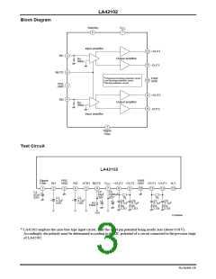
External Components
C1, C2 : Input coupling capacitors, for which 4.7µF or less is recommended. LA42102 employs the zero-bias type
input circuit, with the input pin potential being nearly zero. Accordingly, the polarity must be determined
according to the DC potential of a circuit connected to the previous stage of LA42102.
C3
C4, R1 : Capacitor and resistor for mute. C4 is necessary even when the mute function is not used.
C5 : Power capacitor.
: Capacitor for starting time of the ripple filter and amplifier, for which 47µF is recommended.
C6 to C9 : Capacitor and resistor for oscillation prevention. For C6 to C9, the polyester film capacitor with superior
R2 to R5 temperature characteristics (Mylar capacitor) is recommended. Use R2 to R5 of 2.2Ω along with the
capacitor.
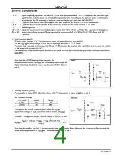
1. Mute function (pin 6)
With the pin 6 voltage of 1.7V (minimum) or more, the mute function is turned ON.
Set the V application voltage so that the pin 6 voltage becomes. 1.7V or more.
M
The mute time constant is determined by R1 and C4. Determine the constant after careful review because it is related
to the pop sound at mute ON/OFF.
C4 is necessary even when the mute function is not used because it is related to the pop sound when the amplifier is
turned ON.
Note that the MUTE pin (pin 6) incorporates the
Mute
anti-electrostatic diode, allowing the current to flow through the
diode when the potential of V
pin 6.
7 pin decreases below that of
V
CC
CC
R1
C4
2kΩ
V
6
M
+
20kΩ
10µF
2kΩ
2. Standby function (pin 5)
The amplifier is turned ON when the voltage of 2.5V (minimum) or more is applied to pin 5.
Pin 5 control voltage
Standby
Pin 5 voltage
0 to 0.5
Amplifier
OFF
Standby
ON
V
CC
2.5 to 15
ON
OFF
2V
BE
R
STB
15kΩ
To suppress the inrush current to pin 5 when the V
STB
application voltage is high, insert the control resistor (R
V
5
S
).
STB
30kΩ
1.5kΩ
Example : Tosuppress the pin 5 inrush current to 500µA or less
Applied voltage (V
) -2V (About 1.4V)
STB BE
500µA
R
STB
=
-15kΩ
Note that the standby pin (pin 5) incorporates the anti-electrostatic diode, allowing the cu orrent to flow through the
diode when the potential of V pin 7 decreases below that of pin 5.
CC
No.A0494-4/8

 SANYO [ SANYO SEMICON DEVICE ]