LA1245
Notes on LA1245 usage
1. When suddenly tuned to a broadcasting station of intermediate or high field strength, a large current of high frequency
flows into the signal meter circuit, causing the local oscillator malfunctions and abnormal noises.
To eliminate this :
· Use R ≥240Ω for manual tuning type.
208
· Use R ≥82Ω, and use the local oscillation coil at the 1/3 tap (except SW) for electronic tuning type (which uses a
208
narrow band filter).
2. Use the bias on the condition RF V ≤IF V , since abnormal noise levels might be caused when detuning a strong
CC
CC
input on the codition RF V >IF V
.
CC
CC
3. Use the signal meter driving output (V ) at V ≤V –2 (V) to avoid saturation caused by V .
CC
SM
SM
CC
4. Use 1/2 or more tap of LW and MW oscillation coil to improve S/N and the detuning characteristics of the distortion
ratio.
5. Use the full-tap of SW oscillation coil, to allow the sag in oscillation power by the decreasing of Q.
6. Avoid the coupling of the antenna tuning circuit and the local oscillating circuit so as not to leak the local oscillation
into the antenna tuning circuit.
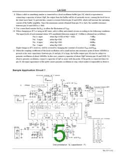
7. Connect the detection capacitor C between pin 13 (output) and pin 14 (V ) to avoid the leakage of the IF signal
113
CC
into the GND line. Connection between pin 13 and pin 12 (GND) increases the tweet interference and deteriorates the
usable sensitivity.
Moreover, depending on the positions of C and the bar antenna, higher harmonics having twice or three times the
113
frequency of the IF signal may pass into the antenna and cause tweet interference, and in extreme cases oscillation
might be cause. To prevent this :
· Shorter lead wires and connect them near 13 and 14 pins.
· Place C far from the antenna.
113
No.737-4/11

 SANYO [ SANYO SEMICON DEVICE ]