LA1143
Continued from preceding page.
output will be omitted, since they are the same as those used in conventional quadrature detector ICs ( such as LA1230,
LA1231N).
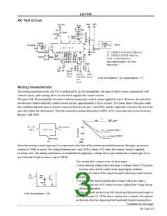
The inverted output of the signal strength indication output is obtained as illustrated below.
By referring to the illustration, V is given by the formula : V =V –(I +I –aI )R –V .
14 BE
14
r
0
1
2
L
Conditions are : V ≈4.9V, I ≈0.2mA, a≈2, R =22kΩ, V ≈0.6V, I =V /R ,
15 15-G
r
0
L
BE
1
I =V /R
, where V is a constant equal to 4.1V (typ.) for medium or lower
16
2
16 16-G
signal input levels, where the muting drive output is required. Since the V
15
increases proportionally to the increase of the input signal strength, I1 will also
increase. Therefore the V will decrease with increasing signal strength. Thus the
14
required muting drive output can be obtained by selecting proper values of R
15-G
and R
.
16-G
For example, the muting drive output moves toward strong input signal level if th R
is decreased, or the muting
16-G
drive output becomes zero due to the offset current I under a weak signal input condition, if the R
is increased to
O
16-G
infinity (namely pin 16 is opened). However the muting drive output caused by a hole detector still exists in this case. In
creasing R decreases the slope of the curve for the muting drive output vs. antenna signal input level, or decreasing
15-G
the R
increases the slope of the curve. Furthermore, varying the value of a resistor connected between the muting
15-G
drive output (pin 14) and the muting control input (pin 6) changes the value of the muting control current required to
obtain the same muting drive output, accordingly a slope of curve for muting attenuation vs. antenna signal input level is
also changed.
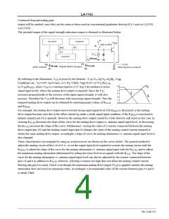
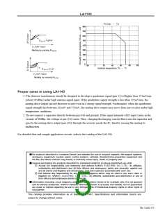
These characteristics investigated by using an actual receiver are shown on the curves below. The general method to
adjust the muting circuit of the LA1143 is : to set the signal input level required to actuate the muting circuit with the
R
, to adjust the slope of the curve for the muting attenuation vs. antenna signal input with the R
, and to adjust
15-G
16-G
the maximum muting attenuation (determined by setting the noise level at no signal) with the R . The slope of the
5-G
curve for the muting attenuation vs. antenna signal input level can also be adjusted by the resistor connected between
pins 14 and 6 in addition to R
, however, selecting a resistor too high does not allow the muting control current
15-G
flowing into pin 6 to reach 120µA even though the maximum muting drive output (V ) is applied, namely the muting
14
attenuation does not reach its maximum value. Accordingly a recommended value of the resistor between pins 14 and 6
is about 22kΩ.
No.1140-4/5

 SANYO [ SANYO SEMICON DEVICE ]