32-BIT TIMERS
S3C4510B
TIMER OPERATION GUIDELINES
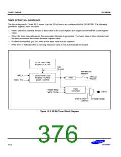
The block diagram in Figure 11-2 shows how the 32-bit timers are configured in the S3C4510B. The following
guidelines apply to timer functions.
— When a timer is enabled, it loads a data value to its count register and begins decrement the count register
value.
— When the timer interval expires, the associated interrupt is generated. The base value is then reloaded and
the timer continues decrement its count register value.
— If a timer is disabled, you can write a new base value into its registers.
— If the timer is halted while it is running, the base value is not automatically re-loaded.
32-Bit Timer Data
Register (TDATAn)
Auto
Re-load
INTPND and
INTMSK
fMCLK
32-Bit Timer Count
Register (TCNTn)
[Down Counter]
Interrupt
Request
PND
TMOD.TEn
Pulse
Generator
TMOD.TMDn
TMOD.TCLRn
TOUTn
Port 16, Port 17
Data Out
IOPCON.TOENn
Figure 11-2. 32-Bit Timer Block Diagram
11-2

 SAMSUNG [ SAMSUNG ]