S3C4510B
32-BIT TIMERS
11 32-BIT TIMERS
OVERVIEW
The S3C4510B has two 32-bit timers. These timers can operate in interval mode or in toggle mode. The output
signals are TOUT0 and TOUT1, respectively.
You enable or disable the timers by setting control bits in the timer control register, TCON. An interrupt request is
generated whenever a timer count-out (down count) occurs.
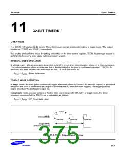
INTERVAL MODE OPERATION
In interval mode, a timer generates a one-shot pulse of a preset timer clock duration whenever a time-out occurs.
This pulse generates a time-out interrupt that is directly output at the timer's configured output pin (TOUTn). In
this case, the timer frequency monitored at the TOUTn pin is calculated as:
fTOUT = fMCLK / Timer data value
TOGGLE MODE OPERATION
In toggle mode, the timer pulse continues to toggle whenever a time-out occurs. An interrupt request is generated
whenever the level of the timer output signal is inverted (that is, when the level toggles). The toggle pulse is
output directly at the configured output pin.
Using toggle mode, you can achieve a flexible timer clock range with 50% duty. In toggle mode, the timer
frequency monitored at the TOUTn pin is calculated as follows:
fTOUT = fMCLK / (2 * Timer data value)
fTOUT
Interval Mode
Time-out
Time-out
Time-out
fTOUT
Toggle Mode
(Initial TOUTn is 0)
Figure 11-1. Timer Output Signal Timing
11-1

 SAMSUNG [ SAMSUNG ]