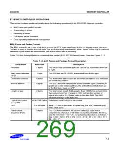
S3C4510B
ETHERNET CONTROLLER
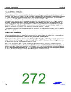
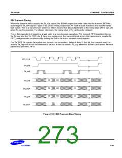
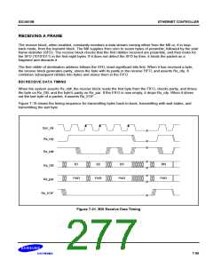
BDI Transmit Timing
When the transmit block asserts the Tx_rdy signal, the BDMA engine can write data into the transmit FIFO by
asserting the Tx_wr# signal. Figure 7-15 shows timing sequences for back-to-back transfers and transfers with
wait states. This is a synchronous interface, which means that data is latched in at the rising edge of the Sys_clk
when Tx_wr# is asserted. For slower interfaces, the rising edge of Tx_wr# can be delayed.
This is the equivalent of asserting a wait state in a synchronous operation. The transmit FIFO machine checks
the Tx_par and the Tx_EOF bits. If there is a parity error, the transmit block aborts the transmission, resets the
FIFO, and generates an interrupt by setting the TxPar bit in the transmit status register.
The Tx_EOF bit signals the end of one frame to be transmitted. When it detects this bit, the transmit block de-
asserts Tx_rdy until it has transmitted the packet. It then re-asserts Tx_rdy when the BDMA can transfer the next
packet into the MAC FIFO.
SYS_CLK
Rx_rdy
Rx_wr#
B1
B1
B1
B2
B2
B2
B3
B3
B3
Rx_DB
Rx_BE#
Rx_par
Rx_EOF
Figure 7-17. BDI Transmit Data Timing
7-51

 SAMSUNG [ SAMSUNG ]