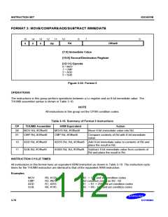
INSTRUCTION SET
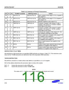
OP H1 H2
S3C4510B
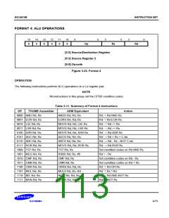
Table 3-12. Summary of Format 5 Instructions
THUMB Assembler
ARM Equivalent
Action
00
0
1
ADD Rd, Hs
ADD Rd, Rd, Hs
Add a register in the range 8-15 to a register in
the range 0-7.
00
1
0
ADD Hd, Rs
ADD Hd, Hd, Rs
Add a register in the range 0-7 to a register in
the range 8-15.
00
01
1
0
1
1
ADD Hd, Hs
CMP Rd, Hs
ADD Hd, Hd, Hs
CMP Rd, Hs
Add two registers in the range 8-15.
Compare a register in the range 0-7 with a
register in the range 8-15. Set the condition
code flags on the result.
01
1
0
CMP Hd, Rs
CMP Hd, Rs
Compare a register in the range 8-15 with a
register in the range 0-7. Set the condition
code flags on the result.
01
10
10
00
00
00
1
0
1
0
1
1
1
1
0
1
0
1
CMP Hd, Hs
MOV Rd, Hs
MOV Hd, Rs
MOV Hd, Hs
BX Rs
CMP Hd, Hs
MOV Rd, Hs
MOV Hd, Rs
MOV Hd, Hs
BX Rs
Compare two registers in the range 8-15. Set
the condition code flags on the result.
Move a value from a register in the range 8-15
to a register in the range 0-7.
Move a value from a register in the range 0-7
to a register in the range 8-15.
Move a value between two registers in the
range 8-15.
Perform branch (plus optional state change) to
address in a register in the range 0-7.
BX Hs
BX Hs
Perform branch (plus optional state change) to
address in a register in the range 8-15.
INSTRUCTION CYCLE TIMES
All instructions in this format have an equivalent ARM instruction as shown in Table 3-12. The instruction cycle
times for the THUMB instruction are identical to that of the equivalent ARM instruction.
THE BX INSTRUCTION
BX performs a branch to a routine whose start address is specified in a Lo or Hi register.
Bit 0 of the address determines the processor state on entry to the routine:
Bit 0 = 0
Bit 0 = 1
Causes the processor to enter ARM state.
Causes the processor to enter THUMB state.
NOTE
The action of H1 = 1 for this instruction is undefined, and should not be used.
3-74

 SAMSUNG [ SAMSUNG ]