PM9904BPD
ssaammeess
where:
The simplest way to implement the creep threshold is to relate
it to the time between meter pulses. If the time between pulses
is more than the limit, the energy accumulator is cleared.
Vnom is the mains voltage and correspond to 14µA in the
voltage inputs of the SA9904B.
Imax is the maximum mains current to be measured and
correspond to 16µA on the current inputs of the SA9904B.
Pulse rate of meter at rated conditions (Hz):
Rf = ( Vnom x Imax / 1000 ) x ( Mpr / 3600 )
The pulse rate required for a meter is usually expressed in
pulses/kWh. A single pulse on the LED is mostly a fraction of a
kWhandisconvertedtoenergyinWs/pulse
where:
Vnom is the mains voltage and correspond to 14µA in the
voltageinputs.
EnergyperLEDpulseis(Ws/pulse):
Eppenergy= 1000x3600/ Mpr
Imax is the maximum mains current to be measured and
correspondto16µAonthecurrent inputsof thedevice.
Mpristhemeterpulserateinpulses/kWh.
where:
EppisenergyperLEDpulse
Mpristhemeterpulserateormeterconstant inpulses/kWh
Creepthresholdtime(s):
Ct =1/(Cc/ Imax) xRf
The threshold is calculated by dividing the energy represented
by a LED pulse by the energy per register count.
where:
Cc is the specified creep current; energy below this value is
discarded.
Imax is the maximum mains current to be measured and
correspondto16µAonthecurrent inputsof thedevice.
Rf istheratedcurrent frequency.
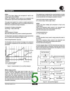
Active energy threshold = Epp / Epc
The threshold is thus the amount of energy to be measured
(accumulated / integrated) by the meter before a LED pulse is
generated.
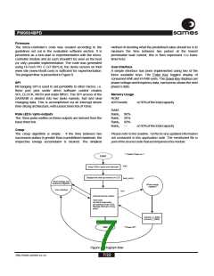
The flow diagram (figure 6) for the timer interrupt shows how
the time between pulses is measured, if the time since the last
pulse is more than the time measured, the integrator is reset
andanewcount downisstarted.
Pulse threshold
Threshold value subtracted
from integrator
Start Timer Interrupt
Integrator zero
No
Yes
Yes
If LED On
Decrement LED ON timer
Switch LED off
Pulse LED
Pulse Generated
Reg 8 add to Integrator
If LED ON Timer = 0
Reg 4 add to Integrator
Reg 0 add to Integrator
Figure 5: Implementation of an overflow integrator
No
Yes
Yes
If creep timer > 0
If creep timer = 0
Decrement creep timer
Meter creep current
For the SA9904B meter creep must be taken care of in
software. From the explanation above on how to generate
pulses, the meter must also be prevented from pulsing in
cases where the energy measured is less than the creep
threshold as per the meter specification. The creep current is
defined as the limit for measured energy, any energy less than
the creep threshold is discarded, and energy above the creep
thresholdismeasured.
Load creep timer
Reset integrator
No
Exit Interrupt
Figure 6: Interrupt flow diagram
5/22
http://www.sames.co.za

 SAMES [ SAMES ]