[SML-D14DWT86(C)]
[Data Sheet]
ꢀꢀꢀꢀ
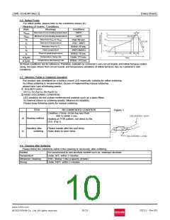
4-6. Reflow Profile
ꢀ For reflow profile, please refer to the conditions below:(※)
・Meaning of marks, Conditions
Mark
Meanings
Conditions
180℃
Maximum of pre-heating temperature
Tsmax
Minimum of pre-heating temperature
Time from Tsmin to Tsmax
Reference temperature
Retention time for TL
140℃
Tsmin
Ts
Over 60 sec.
230~260℃
Within 40 sec.
260℃(MAX.)
Within 10 sec.
Under 3℃/sec.
Within -3℃/sec.
TL
tL
Peak temperature
TP
Time for peak temperature
Temperature rising rate
Temperature decreasing rate
tP
ΔTR/Δt
ΔTD/Δt
※Above conditions are for reference. Therefore, evaluate by customer’s own circuit boards and reflow furnaces before
using, because stress from circuit boards and temperature variations of reflow furnaces vary by customer’s own
conditions.
4-7. Attention Points in Soldering Operation
ꢀThis product was developed as a surface mount LED especially suitable for reflow soldering.
So reflow soldering is recommended. Incase of implementing manual soldering,
please take care of following points.
① SOLDER USED
Sn-Cu, Sn-Ag-Cu, Sn-Ag-Bi-Cu
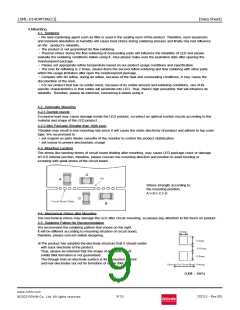
②HAND SOLDERING CONDITION
LED products do not contain reinforcement material such as a glass fillers.
So thermal stress by soldering greatly influence its reliability.
Please keep following points for manual soldering.
ITEM
RECOMMENDED CONDITION
ꢀFigure-1
Condition ) Temp. of iron top less than
400 ℃ within 3 sec.
Heating on PCB pattern, not direct to the
LED. (Fig-1)
a) Heating method
Handling after
Please handle after the part temp.
Goes down to room temp.
b)
soldering
4-8. Cleaning after Soldering
ꢀPlease follow the conditions below if the cleaning is necessary after soldering.
Solvent
We recommend to use alcohols solvent such as, isopropyl alcohols
Under 30℃ within 3 minutes
Temperature
Ultrasonic Cleaning
Drying
15W/Below 1 liter (capacity of tank)
Under 100℃ within 3 minutes
www.rohm.com
©2023 ROHM Co., Ltd. All rights reserved
10/15
2023.3 - Rev.001
ロ
图片预览")
 ROHM [ ROHM ]