Datasheet
RGTVX2TS65
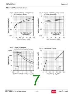
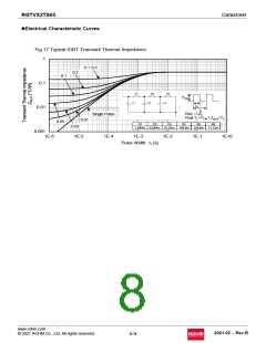
lElectrical Characteristic Curves
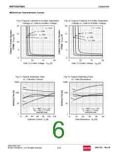
Fig.9 Typical Collector to Emitter Saturation
Voltage vs. Gate to Emitter Voltage
Fig.10 Typical Collector to Emitter Saturation
Voltage vs. Gate to Emitter Voltage
20
20
Tj = 175ºC
Tj = 25ºC
IC = 120A
IC = 120A
15
15
IC = 60A
IC = 60A
IC = 30A
IC = 30A
10
10
5
0
5
0
5
10
15
20
5
10
15
20
Gate To Emitter Voltage : VGE [V]
Gate To Emitter Voltage : VGE [V]
Fig.11 Typical Switching Time
vs. Collector Current
Fig.12 Typical Switching Time
vs. Gate Resistance
1000
1000
td(off)
td(off)
tf
100
10
1
100
10
1
tf
td(on)
tr
td(on)
tr
VCC = 400V, VGE = 15V,
RG = 10Ω, Tj = 175ºC
Inductive load
VCC = 400V, VGE = 15V,
IC = 60A, Tj = 175ºC
Inductive load
0
20 40 60 80 100 120
Collecter Current : IC [A]
0
10
20
30
40
50
Gate Resistance : RG [Ω]
www.rohm.com
© 2021 ROHM Co., Ltd. All rights reserved.
2021.02 - Rev.B
6/9

 ROHM [ ROHM ]