LM393DR/PWR/DGKR,LM2903DR/PWR/DGKR/VQDR/VQPWR
LM339DR/PWR,LM2901DR/PWR/VQDR/VQPWR
Technical Note
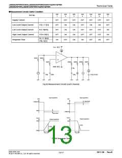
●Measurement Circuit2 Switch Condition
SW
1
SW
2
SW
3
SW
4
SW
5
SW
6
SW
7
SW No.
Supply Current
―
OFF
OFF
OFF
OFF
OFF
ON
ON
ON
OFF
ON
ON
ON
OFF
OFF
OFF
OFF
OFF
ON
OFF
ON
OFF
OFF
ON
Low Level Output Current
Low Level Output Current
High Level Output Current
VOL=1.5[V]
IOL=4[mA]
VOH=36[V]
OFF
OFF
OFF
OFF
ON
RL=5.1[kΩ]
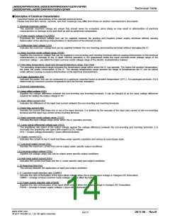
Response Time
ON
OFF
ON
ON
OFF
ON
OFF
VRL=5[V]
Vcc 5[V]
A
-
+
SW1 SW2
SW3
SW4 SW5 SW6 SW7
GND 0[V]
RL
A
V
VIN- VIN+
VRL
VOL/VOH
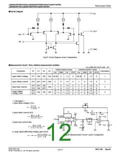
Fig.89 Measurement Circuit2 (each channel)
Input waveform
VIN
Input waveform
VIN
+100[mV]
over drive
0[V]
0[V]
+100[mV]
over drive
VUOT
VUOT
5[V]
Output waveform
2.5[V]
Output waveform
5[V]
2.5[V]
0[V]
0[V]
Tre LH
Tre LH
Fig.90 Response Time
www.rohm.com
© 2011 ROHM Co., Ltd. All rights reserved.
2011.06 - Rev.B
13/17

 ROHM [ ROHM ]