Video ICs
BA7149F
Operation notes
•
(1) H.OSC free-run frequency and capture range
The free-run frequency is determined by the 115kΩ
resistor connected between pin 15 and GND. The cap-
ture range is varied by the resistors and capacitor con-
nected to pins 14 and 15.
(3) Use with PAL systems
In PAL systems, change the value of the resistor con-
nected between pin 6 and GND to 18kΩ.
(4) PCB pattern
The large-signal systems and small-signal systems in
the IC have been kept separate, and the external wring
must also be done in such a way to prevent interfer-
ence from occurring. In particular, to prevent the FBT
return current from interfering with the V. OSC circuit
on pins 6 and 7, do not directly connect the pin 4 GND
and pin 6 and 7 GND.
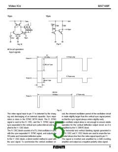
The free-run frequency and capture range for this IC
are guaranteed for these circuit constant values, and
we recommend that you use them. The resistor 115kΩ
connected between pin15 and GND should have a tol-
erance of ± 2%, and a temperature coefficient of ±
100ppm or lower.
(2) V.OSC free-run frequency
The V.OSC free-run frequency is determined by the
15kΩ resistor connected between pin 6 and GND, and
the 0.1µF capacitor connected between pin 7 and
GND.
VCC
G
The free-run frequency and capture range for this IC
are guaranteed for these circuit constant values, and
we recommend that you use them. The resistor 15kΩ
connected between pin 6 and GND should have a tol-
erance of ± 2%, and a temperature coefficient of ±
100ppm or lower, and the capacitor connected
between pin 7 and GND should have a tolerance of ±
5%, and a temperature coefficient of ± 250ppm or
lower.
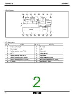
1
2
3
4
5
6
7
8
16
15
14
13
12
11
10
9
FBT
Do not connect pin 4 GND
to pin 6 and 7 GND.
Fig.14
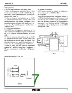
External dimensions (Units: mm)
•
10.0 ± 0.2
16
1
9
8
1.27 0.4 ± 0.1
0.3Min.
0.15
SOP16
7

 ROHM [ ROHM ]