BA10358xx, BA10324Axx, BA2904xxx, BA2904Sxxx, BA2904Wxx
BA2902xx, BA2902Sxx
Datasheet
Description of Electrical Characteristics
Described below are descriptions of the relevant electrical terms used in this datasheet. Items and symbols used are also
shown. Note that item name and symbol and their meaning may differ from those on another manufacturer’s document or
general document.
1. Absolute maximum ratings
Absolute maximum rating items indicate the condition which must not be exceeded. Application of voltage in excess of absolute
maximum rating or use out of absolute maximum rated temperature environment may cause deterioration of characteristics.
1.1 Power supply voltage (VCC-VEE)
Indicates the maximum voltage that can be applied between the positive power supply terminal and negative power
supply terminal without deterioration or destruction of characteristics of internal circuit.
1.2 Differential input voltage (Vid)
Indicates the maximum voltage that can be applied between non-inverting and inverting terminals without damaging
the IC.
1.3 Input common-mode voltage range (Vicm)
Indicates the maximum voltage that can be applied to the non-inverting and inverting terminals without deterioration
or destruction of electrical characteristics. Input common-mode voltage range of the maximum ratings does not assure
normal operation of IC. For normal operation, use the IC within the input common-mode voltage range characteristics.
1.4 Power dissipation (Pd)
Indicates the power that can be consumed by the IC when mounted on a specific board at the ambient temperature 25℃
(normal temperature). As for package product, Pd is determined by the temperature that can be permitted by the IC in
the package (maximum junction temperature) and the thermal resistance of the package.
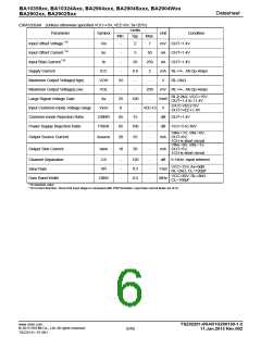
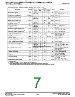
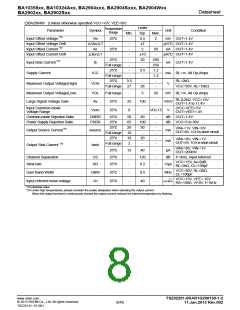
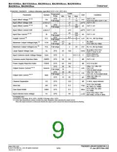
2. Electrical characteristics
2.1 Input offset voltage (Vio)
Indicates the voltage difference between non-inverting terminal and inverting terminals. It can be translated into the
input voltage difference required for setting the output voltage at 0 V.
2.2 Input offset voltage drift (△Vio/△T)
Denotes the ratio of the input offset voltage fluctuation to the ambient temperature fluctuation.
2.3 Input offset current (Iio)
Indicates the difference of input bias current between the non-inverting and inverting terminals.
2.4 Input offset current drift (△Iio/△T)
Signifies the ratio of the input offset current fluctuation to the ambient temperature fluctuation.
2.5 Input bias current (Ib)
Indicates the current that flows into or out of the input terminal. It is defined by the average of input bias currents at
the non-inverting and inverting terminals.
2.6 Circuit current (ICC)
Indicates the current that flows within the IC under specified no-load conditions.
2.7 Maximum Output Voltage(High)/ Maximum Output Voltage(Low) (VOH/VOL)
Indicates the voltage range of the output under specified load condition. It is typically divided into high-level output
voltage and low-level output voltage. High-level output voltage indicates the upper limit of output voltage while
Low-level output voltage indicates the lower limit.
2.8 Large signal voltage gain (Av)
Indicates the amplifying rate (gain) of output voltage against the voltage difference between non-inverting terminal
and inverting terminal. It is normally the amplifying rate (gain) with reference to DC voltage.
Av = (Output voltage fluctuation) / (Input offset fluctuation)
2.9 Input common-mode voltage range (Vicm)
Indicates the input voltage range where IC normally operates.
2.10 Common-mode rejection ratio (CMRR)
Indicates the ratio of fluctuation of input offset voltage when the input common mode voltage is changed. It is
normally the fluctuation of DC.
CMRR = (Change of Input common-mode voltage)/(Input offset fluctuation)
www.rohm.com
© 2013 ROHM Co., Ltd. All rights reserved.
TSZ22111・15・001
TSZ02201-0RAR1G200130-1-2
11.Jan.2013 Rev.002
10/45

 ROHM [ ROHM ]