POWER DISSIPATION
SC-88A
Ver. B
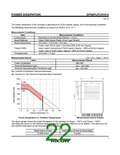
The power dissipation of the package is dependent on PCB material, layout, and environmental conditions.
The following conditions are used in this measurement.
Measurement Conditions
Item
RICOH Evaluation Board
Environment
Mounting on Board (Wind Velocity = 0 m/s)
Glass Cloth Epoxy Plastic (Double-Sided Board)
Board Material
Board Dimensions
40 mm × 40 mm × 1.6 mm
Top Side: Approx. 50%
Bottom Side: Approx. 50%
φ 0.5 mm × 44 pcs
Copper Ratio
Through-holes
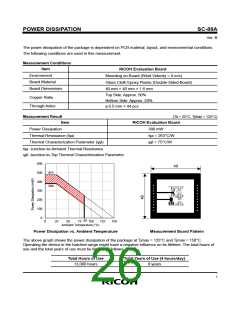
Measurement Result
(Ta = 25°C, Tjmax = 125°C)
Item
RICOH Evaluation Board
380 mW
Power Dissipation
Thermal Resistance (θja)
θja = 263°C/W
ψjt = 75°C/W
Thermal Characterization Parameter (ψjt)
θja: Junction-to-Ambient Thermal Resistance
ψjt: Junction-to-Top Thermal Characterization Parameter
600
40
500
400
300
200
100
0
475
380
85
0
25
50
75
100
125
150
Ambient Temperature (°C)
Power Dissipation vs. Ambient Temperature
Measurement Board Pattern
The above graph shows the power dissipation of the package at Tjmax = 125°C and Tjmax = 150°C.
Operating the device in the hatched range might have a negative influence on its lifetime. The total hours of
use and the total years of use must be limited as follows:
Total Hours of Use
Total Years of Use (4 hours/day)
13,000 hours
9 years
i

 RICOH [ RICOH ELECTRONICS DEVICES DIVISION ]