RT8802A
For example, assuming the negative inductor current is
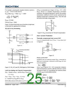
If RADJ is connected as in Figure 14, RADJ = R1 + (R2//
RNTC), which is a negative temperature correlated
resistance. By properly selecting R1 and R2, the positive
temperature coefficient of DCR can be canceled by the
negative temperature coefficient of RADJ. Thus the load
line will be thermally compensated.
ILX_50% = −5A at no load, then for
RCSN 330Ω, RADJ = 160Ω, VOUT = 1.300V
1.3V
− 5A ×1mΩ
330Ω
≥
R
CSN2
RCSN2 ≤ 85.8kΩ
ADJ
Choose RCSN2 = 82kΩ
R1
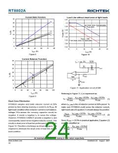
Figure 10 shows that dead zone of load line at light load
is eliminated by applying this technique.
R
ADJ
R
R2
NTC
VR_HOT & VR_FAN Setting
V
CC
5V
Figure 14. RADJ Connection for Thernal Compensation
+
R1
Q1
Q2
Q3
CMP
Over Current Protection
-
0.39 x V
0.33 x V
CC
TSEN
V
TSEN
+
Thermally compensated total current OCP
CMP
-
CC
VTCOC is compared with VADJ. If VADJ > VTCOC then OCP
R
NTC
+
is triggered.
CMP
-
0.28 x V
ADJ
CC
Figure 12
IMAX(1V)
R1
V
TSEN
+
TCOC
OC
V
is inversely proportional
CMP
TSEN
-
to Temperature.
R2
0.39 x V
0.33 x V
0.28 x V
CC
CC
CC
Figure 15
Phase current OCP
VR_FAN
VR_HOT
RT8802A uses an external resistor RIMAX connected to
IMAX pin to generate a reference current IIMAX for over
current protection :
Temperature
V
IMAX
IIMAX
=
RIMAX
where VIMAX is typical 1.0V . OCP comparator compares
each sensed phase current IX with this reference current
as shown in Figure 16. Equivalently, the maximum phase
current ILX(MAX) is calculated as below:
Figure 13. VR_HOT and VR_FANSignal vs TSENVoltage
Load Line Setting and Thermal Compensation
VADJ = Sum(IX) x RADJ = (DCR x RADJ / RCSN) x IOUT
1
3
1
2
= LL x IOUT
IX(MAX)
=
IIMAX
VOUT = VDAC − VADJ = VDAC − LL x IOUT
LL = DCR(PTC) x RADJ(NTC) / RCSN
DCR is the inductor DCR which is a PTC resistance.
V
IMAX
RIMAX
3
2
3
2
=
IIMAX
=
×
IX(MAX)
RCSNX
RLX
RCSNX
DCRX
V
IMAX
RIMAX
3
2
=
×
=
×
×
ILX(MAX) IX
All brandname or trademark belong to their owner respectively
DS8802A-04 August 2007
www.richtek.com
25

 RICHTEK [ RICHTEK TECHNOLOGY CORPORATION ]