RT8296A
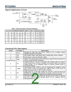
Typical Application Circuit
1
3
V
2
IN
BOOT
RT8296A
VIN
4.5V to 23V
C
100nF
C
BOOT
IN
L
10µF x 2
10µH
V
OUT
SW
3.3V/3A
R
100k
EN
R1
7
8
EN
SS
75k
C
OUT
22µF x 2
5
6
FB
C
C
C
0.1µF
R
SS
C
R2
3.3nF
13k
4, 9 (Exposed Pad)
24k
COMP
GND
C
P
Open
Table 1. Recommended Component Selection
(V) R1 (kW) R2 (kW) R (kW) C (nF) L (mH) C (mF)
OUT
V
OUT
C
C
8
27
62
3
11.8
24
33
3.3
22
15
10
6.8
3.6
3.6
2
22 x 2
22 x 2
22 x 2
22 x 2
22 x 2
22 x 2
22 x 2
5
20
13
3.3
3.3
3.3
3.3
3.3
3.3
3.3
2.5
1.5
1.2
1
75
25.5
10.5
12
12
9.1
5.6
4.3
3.6
12
24
3
12
Functional Pin Description
Pin No.
Pin Name
Pin Function
Bootstrap for High Side Gate Driver. Connect 0.1mF or greater ceramic
capacitor from BOOT to SW pins.
1
BOOT
2
3
VIN
SW
Input Supply Voltage. Must bypass with a suitably large ceramic capacitor.
Phase Node. Connect to external L-C filter.
4,
Ground. The exposed pad must be soldered to a large PCB and connected to
GND for maximum power dissipation.
GND
9 (Exposed Pad)
Feedback Input Pin. This pin is connected to the converter output. It is used to
set the output of the converter to regulate to the desired value via an internal
resistive divider. For an adjustable output, an external resistive divider is
connected to this pin.
5
FB
Compensation Node. COMP is used to compensate the regulation control
loop. Connect a series RC network from COMP to GND. In some cases, an
additional capacitor from COMP to GND is required.
6
7
8
COMP
EN
Enable Input Pin. A logic high enables the converter; a logic low forces the
RT8296A into shutdown mode reducing the supply current to less than 3mA.
Attach this pin to VIN with a 100kW pull up resistor for automatic startup.
Soft-Start Control Input. SS controls the soft-start period. Connect a capacitor
from SS to GND to set the soft-start period. A 0.1mF capacitor sets the
soft-start period to 13.5ms.
SS
www.richtek.com
2
DS8296A-03 March 2011

 RICHTEK [ RICHTEK TECHNOLOGY CORPORATION ]