RT7274/79/80/81
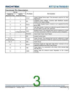
Functional Pin Description
Pin No.
Pin Name
Pin Function
TSSOP-14
SOP-8
(Exposed Pad) (Exposed Pad)
Output Voltage Sense Input. This terminal is used for On-Time
Adjustment.
1
2
3
4
5
--
2
3
4
VOUT
FB
Feedback Input Voltage. Connect with feedback resistive
divider to the output voltage.
5.1V Power Supply Output. Connect a 1μF capacitor from this
pin to GND.
PVCC
SS
Soft-Start Control. Connect an external capacitor between this
pin and GND to set the soft- start time.
5,
Analog Ground. The exposed pad must be soldered to a large
PCB and connected to GND for maximum power dissipation.
GND
9 (Exposed Pad)
6
7
--
1
PGOOD
EN
Open Drain Power Good Output.
Enable Control Input.
8, 9, 15
(Exposed pad)
Power Ground. The exposed pad must be soldered to a large
PCB and connected to PGND for maximum power dissipation.
--
6
7
PGND
SW
10, 11
12
Switch Node.
Bootstrap Supply for High Side Gate Driver. Connect a 0.1μF
capacitor between the BOOT and SW pin.
BOOT
Power Input. It is connected to the drain of the internal high
side MOSFET.
13
14
8
VIN
Supply Input for Internal Linear Regulator to the Control
Circuitry.
--
VINR
Copyright 2013 Richtek Technology Corporation. All rights reserved.
©
is a registered trademark of Richtek Technology Corporation.
DS7274/79/80/81-01 February 2013
www.richtek.com
3

 RICHTEK [ RICHTEK TECHNOLOGY CORPORATION ]