ZULU Modem
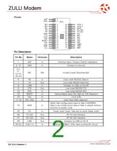
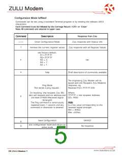
Pinout
Pin Description
Pin No
Name
Direction
Description
1
ANT
In
In
Antenna Input / Output 50ohm Impedance
Connect to Ground
2, 15
GND
3-5,
11,
13-14,
20-24
N/C
N/A
Unused Leave Disconnected.
6
7
RX
TX
In
Out
In
(Low Level RS232) Data in
Low Level RS232 Data Out
Connect to LINK on Pin 28
Low Level RS232 CTS
8
LINK
CTS
9
Out
In
10
12
16
17-18
RTS
Low Level RS232 RTS
RESET
Vcc
In
Device Reset Input (Tie High via 10K Resistor)
+2.2-3.6v
In
DR1-DR2
In
Host Data Rate selection.
When High configuration data is held in EEPROM.
When Low configuration data is held in volatile memory
and lost on power cycle.
19
WRE
In
25
PD
In
Power down mode. Take low to enter Sleep mode
26
27
TX LED
RX LED
LINK
Out
Out
Out
In
RF TX LED indicator
RF RX LED indicator
28
Connect to LINK on Pin 8
29-30
XTAL1-2
Connect 30MHz XTAL here to drive RF Circuit
DS-ZULU Modem-1

 RFSOLUTIONS [ RFSOLUTIONS.LTD ]