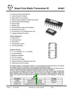
Smart Com Radio Transceiver IC
RF600T
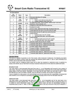
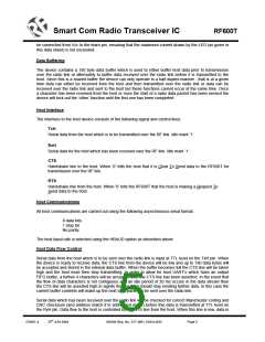
Pin Descriptions
Pin
Number
Name
RxR
Type
Description
Received data from RF module.
Dual Function:
1
In
Out
In
CTS
LOOP
2
1. Clear to send data (to host) when low.
2. Enables loopback mode when low.
In addressed mode: Used to initiate ‘address learn’ and erase
functions. Drives indicator LED.
3
In/Out
LEARN
4
5
6
7
8
In
In
Request to send data (from host) when low.
Connect to 0 volts.
RTS
GND
MODE
TxH
In
Device mode, addressed when high, broadcast when low.
Serial data from the host, to be sent on the RF path.
Serial data from the RF path to be sent to the host.
In
Out
RxH
Dual Function:
Out
In
TxR
HBAUD
9
1. Transmit data to the RF module.
2. Host baud rate select. See notes below.
Dual Function:
Out
In
TXEN
RFBAUD
10
1. Transmit enable (low) for the RF module.
2. RF baud rate select. See notes below.
11
12
13
14
15
16
17
18
Out
In
Receive enable (low) for the RF module.
Telemetry logic input #1. (addressed mode only)
Telemetry logic input #2. (addressed mode only)
Positive supply voltage connection.
RXEN
IN1
In
IN2
In
Vcc
Out
In
Connect to 4MHz, 3 terminal resonator.
OSC2
OSC1
OUT1
OUT2
Connect to 4MHz, 3 terminal resonator.
Out
Out
Telemetry logic output #1. (addressed mode only)
Telemetry logic output #2. (addressed mode only)
Operating Modes
The device is capable of operation in one of two modes, either broadcast or addressed. The following description
describes the features of these mode and assumes two identical system nodes ‘A’ and ‘B’ each consisting of an
RF600T and its associated radio transceiver module.
The RF600T must be configured before power up for either the broadcast or addressed mode of operation by
means of the MODE pin (6). Note that for security, broadcast nodes will not receive data from addressed nodes.
.
Broadcast mode
This mode allows a host generated data block from node ‘A’ to be transmitted and received by any number of
other nodes. This data is received and verified (for correct Manchester coding and CRC) by the other nodes before
being output to their host devices. Alternately, in the same way the other nodes can send data to node ‘A’. Note
that although any node can initiate a transfer, only one direction of transfer can be active at a given time.
Correct reception of a data packet is not acknowledged and the host nodes have the responsibility of ensuring that
data transfers occur as required by operating some form of message protocol over the half duplex data link.
Addressed mode
This mode allows a host generated data block from node ‘A’ to be transmitted and for the data frame to be
addressed to one other network node – in this case we assume node ‘B’. When the data is received by node ‘B’ it
is verified for correct Manchester coding, CRC and for address match and then an acknowledge message is
transmitted back to node ‘A’. Node ‘A’ then outputs a confirmation to the host in the form of the ASCII character ‘C’
DS601-4
25th JUN 2004
©2004 Reg. No. 227 4001, ENGLAND
Page 2

 RFSOLUTIONS [ RFSOLUTIONS.LTD ]