ib technology
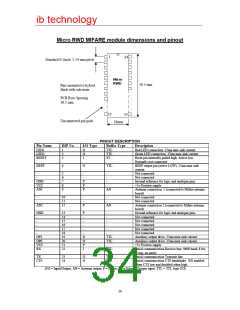
Micro RWD MIFARE module dimensions and pinout
1
24
Standard 0.1inch/ 2.54 mm pitch
Micro
RWD
30.5 mm
Pins mounted to hybrid
flush with substrate.
PCB Row Spacing
18.5 mm
12
13
Unconnected pin pads
18mm
PINOUT DESCRIPTION
Pin Name
LED1
LED2
DIP No.
I/O Type
Buffer Type
Description
1
2
3
O
O
I
TTL
TTL
ST
Red LED connection. 25ma max sink current
Green LED connection. 25ma max sink current
Reset pin internally pulled high. Active low.
Normally not connected
RESET
BEEP
4
O
TTL
BEEP output pin (active LOW), 25ma max sink
current
-
-
5
6
7
8
9
-
-
P
P
P
-
-
-
-
Not connected
Not connected
Ground reference for logic and analogue pins
+5v Positive supply
Antenna connection. 1 (connected to Mifare antenna
board)
GND
VCC
AN1
AN
-
-
10
11
12
-
-
P
-
-
Not connected
Not connected
Antenna connection 2 (connected to Mifare antenna
board)
AN2
AN
GND
-
-
-
-
-
OP1
OP0
VCC
RX
13
14
15
16
17
18
19
20
21
22
P
-
-
-
-
-
-
-
-
-
-
Ground reference for logic and analogue pins.
Not connected
Not connected
Not connected
Not connected
-
Not connected
O
O
P
I
TTL
TTL
-
Auxiliary output drive. 25ma max sink current.
Auxiliary output drive. 25ma max sink current.
+5v Positive supply
Serial communication Receive line. 9600 baud, 8 bit,
1 stop, no parity
TTL
TX
CTS
23
24
O
O
TTL
TTL
Serial communication Transmit line
Serial communication CTS handshake. RX enabled
when CTS low and disabled when high.
(I/O = Input/Output, AN = Antenna output, P = Power, ST = Schmitt Trigger input, TTL = TTL logic I/O)
34

 RFSOLUTIONS [ RFSOLUTIONS.LTD ]