ib technology
Mifare Ultralight (64 byte) Memory Map
4 byte Page
Byte 3
Byte 0
Page 0 (0x00), Serial number
Sn0
Sn1
Int
Sn2
Lock0 Lock1
Bcc0
Page 1 (0x01), Serial number
Page 2 (0x02), Internal/Lock
Bcc1
Page 3 (0x03), One Time Program
32 bit Data
32 bit Data
16 Pages
(4 bytes each)
32 bit Data
32 bit Data
(12 pages)
48 bytes
Read/Write
Data
32 bit Data
32 bit Data
32 bit Data
32 bit Data
32 bit Data
32 bit Data
32 bit Data
Page 15 (0x0F)
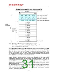
Note: Ultralight card has 7 byte serial number (+ 2 check bytes)
Bcc0 = CT xor Sn0 xor Sn1 xor SN2 (CT = Cascade Tag = 0x88)
Bcc1 = Sn3 xor Sn4 xor Sn5 xor Sn6
The Mifare Ultralight transponder has a different structure to the standard 1k and 4k
byte Mifare transponders. The 64 byte memory is organised as sixteen pages of four bytes
each. The first two pages (and byte 0 of page 3) contain a seven byte serial number (UID)
together with two check bytes. The other “system” bytes are used for locking card features
and providing a number of OTP (One Time Programmable) data bytes. The remaining 12
pages (48 bytes) can be used for general read/write storage.
Despite having a different memory structure, the Ultralight uses the same Mifare
communication protocol except that a cascaded selection procedure is used and the
Authentication procedure is not used for read/write operations. The security Keys are
therefore NOT required for any operations to an Ultralight card. Because of it’s smaller
memory, more basic operation and lower cost, the Ultralight card is typically used for low-
value single applications.
The MicroRWD MF reader module fully supports the Ultralight cards and the read and write
commands have the same format as for the standard cards except that dummy data bytes
(0x00 values) are used for the Key number etc. In addition the “block number” argument
becomes a “page number” parameter.
31

 RFSOLUTIONS [ RFSOLUTIONS.LTD ]