ib technology
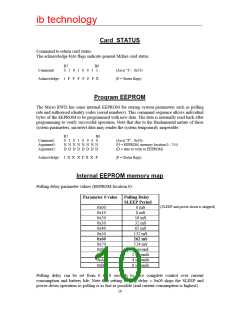
Note that the polling delay parameter must be a valid value (as shown in the table above),
other values will give undefined results.
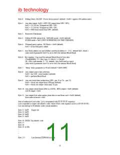
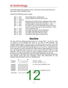
Default RWD EEPROM parameter settings:
Byte 0: 0x60,
Byte 1: 0x03,
Byte 2: Reserved
Byte 3: 0x00
Byte 4: 0x00
Byte 5: 0x01
Byte 6: 0x00
260mS Polling delay / SLEEP period
Aux data output as 9600 baud serial on OP0
MIFARE mode (ICODE mode not supported on this version)
Wiegand NO parity option (only used if Byte 1 = 0x01 / 02)
Aux block address on card (only used if Byte 8 = 0x01)
Key number / type used for internal Block Read of Aux data
(Use Key Code 0 as Key Type A, only used if Byte 8 = 0x01)
“Beep” output delay OFF
Aux output source data is UID (serial number).
Aux output (serial data) directed to OP0 pin.
Aux output serial format, HEX byte format
Byte 7: 0x00
Byte 8: 0x00
Byte 9: 0x00
Byte 10: 0x00
Byte 11: 0x00
Aux data byte order, plain as read from card
Store Keys
The Micro RWD has additional internal storage for 32 Security KEYs. Six byte Key codes
are required to access individual card sectors for any Read or Write operations. This
command sequence allows 6 byte Key codes to be stored at any one of the 32 key code
locations. Factory defaults are Infineon/Philips specified transport key code pairs (Hex FF FF
FF FF FF FF / Hex FF FF FF FF FF FF)) and (Hex A0 A1 A2 A3 A4 A5 / Hex B0 B1 B2 B3
B4 B5) and these are stored in the RWD non-volatile memory during manufacture. Note that
due to the fundamental nature of these Key codes, incorrect values may render the system
inoperable. Only one or two Security key codes are required to unlock a card sector so the
provision of 32 storage locations allows for many possible applications and card uses.
IT IS STRONGLY ADVISED THAT THE KEY CODES IN THE RWD AND STORED ON
THE MIFARE CARD ARE NOT CHANGED UNTIL THE OPERATION OF THE
MIFARE CARD SECURITY IS FULLY UNDERSTOOD.
B7
B0
Command:
Argument1:
0 1 0 0 1 0 1 1
x x x K K K K K
(Ascii “K”, 0x4B)
(K = Key code number, 0 - 31)
Argument2:
Argument3:
Argument4:
Argument5:
Argument6:
Argument7:
D D D D D D D D
D D D D D D D D
D D D D D D D D
D D D D D D D D
D D D D D D D D
D D D D D D D D
(D = data to write to EEPROM, LS byte)
(D = data to write to EEPROM, MS byte)
(F = Status flags)
Acknowledge: 1 X X X F X X F
12

 RFSOLUTIONS [ RFSOLUTIONS.LTD ]