ib technology
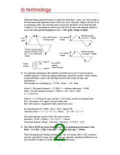
Optimum tuning and performance is achieved when these “steps” are seen exactly at
the maximum and minimum points of the sine wave, the peak voltage will also be at
its maximum value. The antenna series resistor (R) should be set to limit the peak
voltage to 110v maximum in order to give the best Q value and optimum signal-to-
noise ratio (For practical purposes use +/-100v peak voltage as limit).
Detuned antenna.
L too low (<700uH)
Micro RWD driver Low antenna
110v
peak
switching steps
voltage
125kHz correctly tuned
antenna waveform with
Ra = 22 R to limit peak
voltage
Detuned antenna.
L too high (>700uH)
Low antenna
voltage
AN1
MicroRWD
22R
700uH
Antenna
antenna
connection pins
AN2
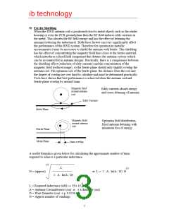
6) For optimum performance the antenna Q should not exceed 20 and to achieve
reliable tuning at 125kHz the antenna inductance should be around 700uH. Higher
Q and inductance values will still function but with a reduced range and
performance.
The formula for calculating Q = 2*π*fL / Rant = 549 / Rant
where f = Resonant frequency, 125 kHz, L = Antenna inductance, 700uH
Rant = Overall antenna resistance = Rdriver + Ra + (Rcu + Rrf)
π = 3.14159 etc
Rdriver = 3.5 R (from IC spec) and Ra = 22 R (series resistor in antenna loop)
Rcu = Resistance of Copper (coil and cable) and
Rrf = RF resistive component (eddy current losses etc)
By measurement at 125kHz, (Rcu + Rrf) = approx 6R
Therefore Rant = 3.5 + 22 + 6 = 31.5 Ohms, Q = 549 / 31.5 = 17
Max peak antenna current (with 22R series resistor),
Iant max = 4Vdd / π*Rant = 20 / π*31.5 = 200ma
Max peak antenna voltage, Uant max = Iant max . (2*π*fL) = 110v
7) The Micro RWD has been designed to work at optimum performance with
Rant = 31.5 (Ra = 22R), Uant max = 110v and Iant max = 200ma.
When designing and winding antenna coils, the wire gauge and it’s DC resistance
must be considered to keep close to the design optimum. Significant differences in
Ra will affect resilience to EMC and overall performance.
2

 RFSOLUTIONS [ RFSOLUTIONS.LTD ]