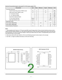
Electrical Characteristics (typical values given for 3.0 Vdc power supply, 25 oC)
Characteristic
Sym
Notes
Minimum
Typical
Maximum
Units
Transmitter Performance
Peak RF Output Power, 450 µA TXMOD Current
Peak Current, 450 µA TXMOD Current
PO
ITP
2
2
2
2
2
3
3
0
dBm
mA
12
2
nd - 4th Harmonic Outputs
-50
-55
dBm
dBm
dBm
µs
5th - 10th Harmonic Outputs
Non-harmonic Spurious Outputs
TX Turn On/Turn Off Times
ASK Output Rise/Fall Times
-50
tON/tOFF
tTR/tTF
IS
12/6
0.1/0.1
µs
Sleep Mode Current
0.7
µA
Power Supply Voltage Range
Power Supply Voltage Ripple
Ambient Operating Temperature
VCC
2.2
-40
3.7
10
85
Vdc
mVP-P
oC
TA
Notes:
1. Typical sensitivity data is based on a 10-3 bit error rate (BER), using DC-balanced data. There are two test methods commonly used to
measure OOK/ASK receiver sensitivity, the “100ꢀ AM” test method and the “Pulse” test method. Sensitivity data is given for both test meth-
ods. See Appendix 3.8 in the ASH Transceiver Designer’s Guide for the details of each test method. The application/test circuit and compo-
nent values are shown on the next page.
2. Data is given with the ASH radio matched to a 50 ohm load. Matching component values are given on the next page.
3. See Table 1 on Page 8 for additional information on ASH radio event timing.
A
S
H
T
r
a
n
s
c
e
i
v
e
r
P
i
n
O
S
M
-
2
0
H
P
a
c
k
a
g
e
D
r
a
w
i
n
g
0
.
2
7
"
0
.
0
8
"
0
.
0
7
"
G
N
D
1
R
F
I
O
(
6
.
8
6
)
(
2
.
0
3
)
(
1
.
8
0
)
1
2
0
0
0
.
.
0
0
2
4
"
"
(
(
0
1
.
.
5
0
1
2
)
)
V
C
C
2
1
1
9
G
C
C
V
P
P
N
D
3
A
G
C
C
3
4
5
6
7
8
9
A
P
1
8
N
N
T
T
R
R
L
L
0
1
0
.
4
0
"
P
K
D
E
T
T
1
1
1
1
1
1
7
6
5
4
3
2
(
1
0
.
1
)
B
B
O
U
C
W
C
A
2
C
M
P
I
N
I
D
T
H
0
.
0
6
"
R
X
D
A
T
A
R
T
E
(
1
.
5
2
)
T
X
M
O
D
T
H
L
D
1
0
.
1
3
"
(
3
.
3
0
)
L
P
F
A
D
J
T
R
H
L
D
2
1
0
1
1
G
N
D
2
R
E
F
2

 RFM [ RF MONOLITHICS, INC ]