X9313
AC Electrical Specifications Over recommended operating conditions, unless otherwise stated.
LIMITS
TYP
SYMBOL
PARAMETER
MIN
100
100
2.9
1
(Note 4)
MAX
UNIT
ns
t
t
t
CS to INC Setup
CI
ID
DI
INC HIGH to U/D Change
U/D to INC Setup
INC LOW Period
ns
µs
t
µs
IL
IH
IC
t
t
INC HIGH Period
1
µs
INC Inactive to CS Inactive
CS Deselect Time (STORE)
CS Deselect Time (NO STORE)
1
µs
t
t
20
ms
ns
CPH
CPH
100
t
INC to V Change
W
5
µs
IW
t
INC Cycle Time
2
µs
CYC
t , t (Note 5)
INC Input Rise and Fall Time
Power-up to Wiper Stable
500
50
µs
R
F
t
(Note 5)
10
10
µs
PU
t
V
(Note 5)
V
Power-up Rate
0.2
V/ms
ms
R
CC
CC
t
(Note 5)
Store Cycle
WR
NOTES:
4. Typical values are for T = +25°C and nominal supply voltage.
A
5. This parameter is not 100% tested.
specification is always in effect. In order to prevent unwanted
tap position changes, or an inadvertent store, bring the CS
and INC high before or concurrently with the VCC pin on
power-up.
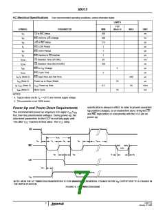
Power-Up and Power-Down Requirements
The recommended power-up sequence is to apply V /V
CC SS
first, then the potentiometer voltages. During power-up, the
data sheet parameters for the DCP do not fully apply until
1ms after V
CC
reaches its final value. The V
ramp
CC
CS
t
CYC
t
t
t
t
t
CPH
CI
IL
IH
IC
90%
90%
INC
U/D
10%
t
t
t
t
R
ID
DI
F
t
IW
(SEE NOTE)
MI
V
W
NOTE: MI IN THE AC TIMING DIAGRAM REFERS TO THE MINIMUM INCREMENTAL CHANGE IN THE V OUTPUT DUE TO A CHANGE IN
W
THE WIPER POSITION.
FIGURE 4. AC TIMING DIAGRAM
FN8177.6
January 15, 2008
7

 RENESAS [ RENESAS TECHNOLOGY CORP ]