R32C/118 Group
1. Overview
1.3
Block Diagram
Figure 1.2 shows a block diagram of the R32C/118 Group.
8
8
8
8
8
8
8
Port P0
Port P1
Port P2
Port P3
Port P4
Port P5
Port P6
Peripheral functions
Timer:
Timer A 16 bits × 5 timers
Timer B 16 bits × 6 timers
Clock generator:
4 circuits
- XIN-XOUT
- XCIN-XCOUT
- On-chip oscillator
- PLL frequency synthesizer
A/D converter:
10 bits × 1 circuit
Standard: 10 inputs
Maximum: 34 inputs (1)
Three-phase motor
controller
D/A converter:
8 bits × 2 channels
Watchdog timer:
15 bits
Serial interface:
9 channels
X-Y converter:
16 bits × 16 bits
DMAC
Multi-master I2C-bus
interface:
CRC calculator (CCITT)
X16 + X12 + X5 + 1
DMAC II
1 channel
Memory
ROM
Intelligent I/O
Time Measurement: 16
Wave generation: 24 (2)
Serial interface:
R32C/100 Series CPU Core
R2R0
R2R0
FLG
INTB
ISP
USP
PC
SVF
SVP
VCT
R3R1
R3R1
R6R4
R6R4
- Variable-length
R7R5
RAM
R7R5
A0
synchronous serial I/O
A0
A1
- IEBus (4)
A1
A2
A2
A3
Multiplier
A3
FB
CAN module:
2 channels
FB
SB
SB
Floating-point unit
Port P15
Port P14
Port P14_1
Port P13
Port P12
Port P11
8
4
8
8
5
(Note 5)
Notes:
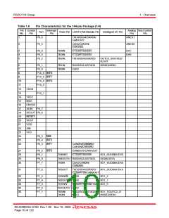
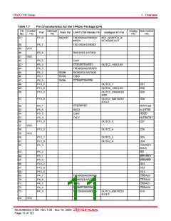
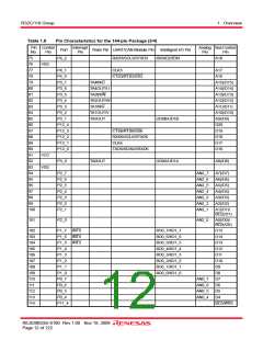
1. 34 inputs are available in the 144-pin package. In the 100-pin package, up to 26 inputs are provided.
2. 24 outputs are available in the 144-pin package. In the 100-pin package, 19 outputs are provided.
3. Eight ports are available in the 144-pin package. In the 100-pin package, five I/O ports and one input-
only port (P9_1) are provided.
4. IEBus is a trademark of NEC Electronics Corporation.
5. Ports P11 to P15 are available in the 144-pin package only.
Figure 1.2
R32C/118 Group Block Diagram
REJ03B0255-0100 Rev.1.00 Nov 19, 2009
Page 8 of 122

 RENESAS [ RENESAS TECHNOLOGY CORP ]