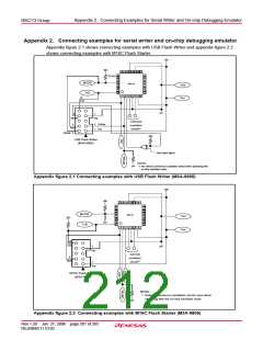
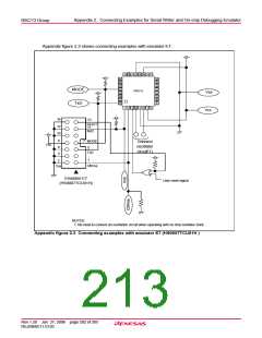
Appendix 2. Connecting Examples for Serial Writer and On-chip Debugging Emulator
R8C/13 Group
Appendix 2. Connecting examples for serial writer and on-chip debugging emulator
Appendix figure 2.1 shows connecting examples with USB Flash Writer and appendix figure 2.2
shows connecting examples with M16C Flash Starter.
24 23 22 21 20 19 18 17
25
26
27
28
16
15
33 kΩ
14
13
MODE
TxD
R8C/13
Vss
Vcc
29
30
12
11
10
9
31
32
1
3 4 5 6 7 8
2
10
TxD
8
7
RESET
Vss
Connect
oscillator
circuit(1)
4
3
1
CNVss
Vcc
RxD
2
MODE
USB Flash Writer
(M3A-0665)
User reset signal
NOTES:
1: No need to connect an oscillation circuit when operating with
on-chip oscillator clock.
Appendix figure 2.1 Connecting examples with USB Flash Writer (M3A-0665)
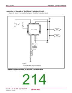
24 23 22 21 20 19 18 17
25
26
27
16
15
14
MODE
TxD
28
13
12
R8C/13
Vss
Vcc
29
30
11
10
9
31
32
2
1
3 4 5 6 7 8
10
TxD
7
Vss
Connet
oscillator
circuit(1)
4
RxD
1
Vcc
M16C Flash Starter
(M3A-0806)
NOTES:
1. Need to connect an oscillation circuit, even when
operating with the on-chip oscillator clock.
Appendix figure 2.2 Connecting examples with M16C Flash Starter (M3A-0806)
Rev.1.20 Jan 27, 2006 page 201 of 205
REJ09B0111-0120

 RENESAS [ RENESAS TECHNOLOGY CORP ]