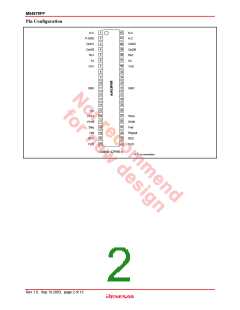
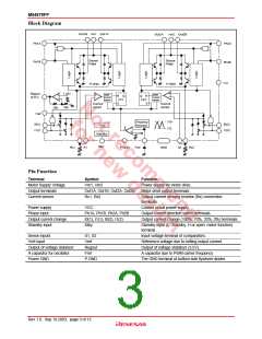
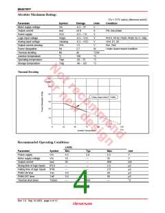
M54679FP
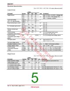
Electrical characteristics
(Ta = 25°C, VCC = 5.0V, VM = 24V unless otherwise noted.)
Control Circuit
Limits
Min.
39
Parameter
Symbol
ICC1
Typ. Max.
Unit Conditions
Stby = H, Ph*A = H, Ph*B = L (Bridge ON)
Supply current
56
27
4.0
73
ICC2
20
40
mA
Stby = H, Ph*A = Ph*B (Bridge OFF)
Stby = L (Standby condition)
ICC3
2.0
2.4
0
6.0
Vcc
0.6
10
Logic input voltage
(Ph, I1, I0, Stby terminals)
Vlogic H
Vlogic L
V
Phase terminal input current I(Ph) H
I(Ph) L
µA
µA
µA
Vin = 5V
Vin = 0V
Vin = 5V
Vin = 0V
Vin = 5V
Vin = 0V
–20
–3.0
I0, I1 terminals input current
I(I0, I1) H
I(I0, I1) L
I(Stby) H
I(Stby) L
I(S)
10
10
–400 –300
Standby terminal input
current
–400 –300 5.0
Current sensing
Comparators input current
–20
–3.0
µA
S1 or S2 terminals input current
(S1 or S2 = 0V, Vref = 5V).
Current sensing
Comparators input voltage
sphere
V(S)
0
VCH(H)
650
V
S1 or S2 terminal input voltage sphere
Vref input current
I(Vref)
500
µA
Input current of Vref
(Vref = 5V, I0 = I1 = 0V)
Vref input voltage sphere
Oscillation frequency of Fref
Voltage stabilizer output
V(Vref)
FC
0
Vcc
40
V
20
30
kHz
V
C = 390pF, Fref terminal oscillation
Iout = -0.1mA – +1mA
Vreg
3.35
475
325
139
3.50
500
350
155
3.65
525
375
171
Current sensing
Comparators threshold
voltage
VCH(H)
VCH(M)
VCH(L)
mV
mV
mV
I0 = L, I1 = L, Vref = 5V (Vref/10*100%)
I0 = H, I1 = L, Vref = 5V (Vref/10*70%)
I0 = L, I1 = H, Vref = 5V (Vref/10*33%)
Output Circuit
(Ta = 25°C, VCC = 5.0V, VM = 24V unless otherwise noted.)
Limits
Parameter
Symbol Min. Typ. Max. Unit Conditions
Output saturation voltage
Output leakage current
VF of flywheel diode (Top)
Vsat
1.6
2.2
V
Top and Bottom at Load current 0.6A.
Ileak
VF(H)
–100
+100 µA
1.7
1.1
0.5
2.0
2.3
1.5
2.0
3.5
V
If = 0.6A
VF of flywheel diode (Bottom) VF(L)
V
If = 0.6A
Turn ON delay of output
Turn OFF delay of output
tdon
tdoff
µS
µS
Time until output become ON since S > Vref
Time until output become OFF since S < Vref
Rev.1.0, Sep.19.2003, page 5 of 12

 RENESAS [ RENESAS TECHNOLOGY CORP ]