3858 Group
(6) Programmable waveform generating mode
■Mode selection
though “H” is output from the CNTR2 pin, “H” output state contin-
ues because an underflow does not occur.
This mode can be selected by setting “100” to the timer Z1 operat-
ing mode bits (bits 2 to 0) and setting “0” to the timer/event
counter mode switch bit (b7) of the timer Z1 mode register (ad-
dress 002816).
•“L” one-shot pulse; Bit 5 of timer Z1 mode register = “1”
The output level of the CNTR2 pin is initialized to “H” at mode se-
lection. When trigger generation (input signal to INT1 pin) is
detected, “L” is output from the CNTR2 pin. When an underflow
occurs, “H” is output. The “L” one-shot pulse width is set by the
setting value to the timer Z1 low-order and high-order. When trig-
ger generating is detected during timer count stop, although “L” is
output from the CNTR2 pin, “L” output state continues because an
underflow does not occur.
■Count source selection
In high-, or middle-speed mode, 1/2, 1/4, 1/8, 1/16, 1/32, 1/64, 1/
128, 1/256, 1/512 or 1/1024 of f(XIN); or f(XCIN) can be selected as
the count source.
In low-speed mode, 1/2, 1/4, 1/8, 1/16, 1/32, 1/64, 1/128, 1/256, 1/
512 or 1/1024 of f(XCIN); or f(XCIN) can be selected as the count
source.
■Precautions
Set the double-function port of INT1 pin and port P42 to input in
this mode.
■Interrupt
The interrupt at an underflow is the same as the timer mode’s.
■Explanation of operation
Set the double function port of CNTR2 pin and port P22 is automati-
cally set to the programmable one-shot generating port in this mode.
This mode cannot be used in low-speed mode.
The operation is the same as the timer mode’s. Moreover the
timer outputs the data set in the output level latch (bit 4) of the
timer Z1 mode register (address 002816) from the CNTR2 pin each
time the timer underflows.
If the value of the CNTR2 active edge switch bit is changed during
one-shot generating enabled or generating one-shot pulse, then
the output level from CNTR2 pin changes.
Changing the value of the output level latch and the timer latch af-
ter an underflow makes it possible to output an optional waveform
from the CNTR2 pin.
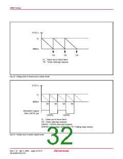
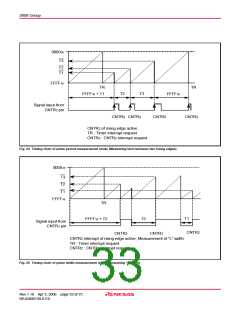
Figure 27 shows the timing chart of the programmable one-shot
generating mode.
■Precautions
■Notes regarding all modes
The double-function port of CNTR2 pin and port P22 is automati-
cally set to the programmable waveform generating port in this
mode.
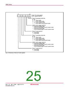
■Timer Z1 write control
Which write control can be selected by the timer Z1 write control
bit (bit 3) of the timer Z1 mode register (address 002816), writing
data to both the latch and the timer at the same time or writing
data only to the latch.
Figure 26 shows the timing chart of the programmable waveform
generating mode.
When the operation “writing data only to the latch” is selected, the
value is set to the timer latch by writing data to the address of timer
Z1 and the timer is updated at next underflow. After reset release, the
operation “writing data to both the latch and the timer at the same
time” is selected, and the value is set to both the latch and the timer
at the same time by writing data to the address of timer Z1.
In the case of writing data only to the latch, if writing data to the
latch and an underflow are performed almost at the same time,
the timer value may become undefined.
(7) Programmable one-shot generating mode
■Mode selection
This mode can be selected by setting “101” to the timer Z1 operat-
ing mode bits (bits 2 to 0) and setting “0” to the timer/event
counter mode switch bit (b7) of the timer Z1 mode register (ad-
dress 002816).
■Count source selection
In high-, or middle-speed mode, 1/2, 1/4, 1/8, 1/16, 1/32, 1/64, 1/
128, 1/256, 1/512 or 1/1024 of f(XIN); or f(XCIN) can be selected as
the count source.
■Timer Z1 read control
A read-out of timer value is impossible in pulse period measure-
ment mode and pulse width measurement mode. In the other
modes, a read-out of timer value is possible regardless of count
operating or stopped.
■Interrupt
The interrupt at an underflow is the same as the timer mode’s.
The trigger to generate one-shot pulse can be selected by the
INT1 active edge selection bit (bit 1) of the interrupt edge selection
register (address 003A16). When it is “0”, the falling edge active is
selected; when it is “1”, the rising edge active is selected.
When the valid edge of the INT1 pin is detected, the INT1 interrupt
request bit (bit 1) of the interrupt request register 1 (address
003C16) is set to “1”.
However, a read-out of timer latch value is impossible.
■Switch of interrupt active edge of CNTR2 and INT1
Each interrupt active edge depends on setting of the CNTR2 ac-
tive edge switch bit and the INT1 active edge selection bit.
■Switch of count source
When switching the count source by the timer Z1 count source selec-
tion bits, the value of timer count is altered in inconsiderable amount
owing to generating of thin pulses on the count input signals.
Therefore, select the timer count source before setting the value
to the prescaler and the timer.
■Explanation of operation
•“H” one-shot pulse; Bit 5 of timer Z1 mode register = “0”
The output level of the CNTR2 pin is initialized to “L” at mode se-
lection. When trigger generation (input signal to INT1 pin) is
detected, “H” is output from the CNTR2 pin. When an underflow
occurs, “L” is output. The “H” one-shot pulse width is set by the
setting value to the timer Z1 register low-order and high-order.
When trigger generating is detected during timer count stop, al-
■Usage of CNTR2 pin as normal I/O port P22
To use the CNTR2 pin as normal I/O port P22, set timer Z1 operat-
ing mode bits (b2, b1, b0) of timer Z1 mode register (address
002816) to “000”.
Rev.1.10 Apr 3, 2006 page 29 of 75
REJ03B0139-0110

 RENESAS [ RENESAS TECHNOLOGY CORP ]